Want to remove ads? Become a MK3OC Club Member today!

Dave b's VXR Powered Gsi Diary

Confirms Jamsport are a bunch of wankers imo.

Good to see it going in the right direction though mate :) Look forward to build pics

Well this diary isn't going to become a slagging match, mainly because it is what it is.

but

So today i cleaned the crank timing pulley up

full

full

full


Yep, sooo that's scrap ( remember i used a puller to get it off, so it wasn't me) laughable really. Obvious difference between an engineer, engineering a solution, like a puller that took 10 mins to make

and a ******* cowboy

Ah well :lol: next thing to sort the snapper turbo stud, I have honestly put this welder away 10 times this project haha

full


snapped stud at the back of the 5 stud flange

full


nut

full


welded

full


nope :lol:

full


Looks like you are getting drilled out!

full


Sorteddddd

full


Turbo saved and ready to go!
 
well all i can say what shite luck your having bud , but bloody nora gd on ya for keeping it going epic read very intresting amazing job bud keep it going
 
well all i can say what shite luck your having bud , but bloody nora gd on ya for keeping it going epic read very intresting amazing job bud keep it going

cheers matey, you don't know the half of it! It incredible really because I am so OCD over the top, and then there is other people who just throw a 100k saab lump in an astra and it will run forever at 350bhp! madness really but tbh, I love a challenge as you can tell and I also like the fact that this is a proper 1 off build and it's all the little custom bits i do without going to far which are my favourite parts of the build. There is gonna be alot more of them to come!

My engine should be back from the machine shop soon hopefully so the story can continue!
 
So I am now able to do a bit of an update, there has been alot of waiting and logistics of purchasing parts etc. pretty boring so I thought I would wait untill all my ducks were in a line! So hear it is!

So after looking into all my options for what parts to buy etc I had decided on the Mahle OE Pistons 0.5mm oversize and the arrows rods. So its time to start getting things organised.

So first thing first was to get the block bored, honed and match to the new pistons. So this went off to a machinest about 45mins away who is known for their good work. Gosney's.
A few days later she was back! I took the oil gallery bungs, WD40 put on the bores and faces to stop rusting and pressure washed this for a very long time to make sure all the metal swarf was out of the block, dried in front of a heater after and put on the stand :)

full

full

full


lovely hone marks!

So the next thing of course is to give it a lick of paint

full


next, it is was time to sort out the oil return to sump from my catch tank. This took alot of thought. the air breather catch tank I bought from pro alloy is baffled so the oil vapour in the gases being breathed out of the engine is seperated and then any excess oil is returned to the sump again.
So i need to get a return welded into the sump. You can drill the block, but I didn't really fancy this lol.

So first, work out where the oil level normally sits, I want the tube above this so I don't have oil sitting in the pipe work unable to return into the sump.

So mocked up the sump, fitted the dipstick and marked the oil level on the inside at the max line

full


made sure the engine was level and then that the ruler was level from the dipstick to the rear of the sump, this where the tube will be going.

full


marked the sump, the line is the oil level, so i drew a 12mm circle above ( this below cause the engine is upside down :lol:) plenty of room! Time to fit the ladder back in. The leh has a ladder in the sump, this strengthens the block which is always a good thing, but it does take up alot of room in the sump....

full


blimey, it is a tight fit! I think the tube will have to be welded flush against the wall of the sump and there no room for any tube to sit inside the sump.
Time to check external room. The only thing round the back of the engine is the driveshaft so I installed that.

full


well i definitely can't have the tube there as the bulk of the driveshaft is there and I will never get a pipe on the outside! Gonna have to look at the other end of the sump

full

full

full


Definitely alot more room! So i transfered the oil level mark to this part of the sump measuring from the upper edge

full

full

full


Good amount of room here, so I went for it! Drilled the hole, stuck the tube in, there is a bit of room the allow for internal welding. All Good!

full


Better start buying some parts

full


:lol:
 
A little update of random odd's and sods tonight. As you can imagine with the time scale of ordering things, getting things sorted etc. There was alot of mini projects gettin done!

Big end bearings turned up

full


Crank main bearings turned up

full


Alot of GM goodies were collected from vauxhall

full


Flywheel was re-faced

full


New crank pulley was needed :lol:, now turned up!

full


And now that I had everything for the bottom end, I took the whole lot for balancing. Silly not to and quite noticeable apprently!

full


Steering rack and master cylinder got rubbed back and primer put on it

full

full

full


Oil pump was stripped, checked, cleaned and painted. Everything was all good!

full

full


Got some stickers from GAZ for my dampers. They don't do the 'Gold' stickers anymore.... That made me sad lol

full

full


Then the rack got paint black and mounted on the car! New genuine gaitors on there and poly bushes powdercoated steering arms. O, and i polished the plate in the middle haha

YUM

full

full

full

full
 
Right, proper progress now. Cylinder head!

I've always wanted to do some port and polishing ( or not as it turns out) of a cylinder head so now is a good time to start.
So first of all Let see what needs doing.

Inlet

full

full


So basically nothing needs doing porting wise. :lol: but the ports have the factory castings on them so these need to be removed. After asking the specialist ( my neighbour) getting rid of the casting marks, but leaving the ports with a rough finish is the way forward. 80 grit is spot on. This apparently is to do with 2 things....

The gold ball theory - air actually flows better over a rough surface than a smooth
The tumble Theory - A rough finish causes the air to tumble, mixing the port injected fuel before entry into the cylinder, better mix, better bang!

So I got the Headphones on, goggles on, die grinder and carbide bits and went to work!

Before and after

full

full


full

full


This is a spot on finish for the inlet so they are all done!

Next the exhaust side

full


NOW there is alot of meat than can go there! I also checked this against the exhaust manifold and the drop is the same again off the manifold gasket, if not slightly more, So at the moment the drop from the cylinder head to the manifold is probably about 10mm! This causes gas speed to slow down and become turbulant.
So as much as i can loose the better as it should improve turbo spool! We all like that.

So I marked the cylinder head

full


and started cutting

full

full


Then started smoothing

full

full


Checked the sizing

full

full


Thats about a far as I want to go. I don't want to remove too much material and risk anything so I am happy.
So let the smoothing commence. The golf ball effect still working on the exhaust side, but it is no as important so I decided I would go for a polished finish instead in order to try and reduce the amount of carbon sticking to the head. But left a little bit of a golf ball finish, almost dimpled. So seemed the best of both worlds.
But also, CAUSE I REALLY WANT TO POLISH SOMETHING! :lol:

On the right, 80 grit, on the left 200 grit

full


Then 400 grit,

full


then the polish buffer bits came out

full


full


full


All done, head is ported, smoothed and slightly polished. Be very interested to see how differently this drive with it but lets be honest, it's a completely different engine lol.

full
 
So what needs to go with my nicely prepped cylinder head, So nice shiny valves. Now these can definitely be polished lol.

Inlets were ok, just a bit dirty.

full


So got the autosol out, shined them up and got them on the polishing wheel

full

full

full


Inlets done, that was easy. the exhausts will not be as easy! They took a long time with the bench grinder running a wire wheel but eventually they were polished up too.
So today I spent all day lapping valves in. The exhaust valves were badly pitted. I was gettin some leakage though the valves so I'm not surprised to find this. A few passes with the course valve grinding past went from this

full


To this

full

full


Many hours and sore hands later....

full


Finally a nice lick of silver to make it look new :)

full


Up to date!
 
Utter lovelyness going on here Dave and soon the most enjoyable part to follow...fitting the many engine parts together to make a single mass of uber power.

Cheers mate, yea I'm really enjoying myself and being able to take my time makes it enjoyable. I've got untill VBOA 21 lol.
Bit nervous about building the bottom end but just gonna take my time and it should be all good.
 
Do you happen to have any pictures of the black foam bit that goes between the rack and body? Can't wait to see this next year
 
Do you happen to have any pictures of the black foam bit that goes between the rack and body? Can't wait to see this next year

Are you running manual rack or Pas? Their different for each.

Manual rack version is super rare!
 
Manual one in the garage to go in the mk3 so will need to make one up from a hard foam
 
Manual one in the garage to go in the mk3 so will need to make one up from a hard foam

I'm sure you might be able to track one down? Find someone who is breaking a boggo spec mk2 or mk3. Use 7zap to get the part number, I'll see what I can find mate.

I found someone breaking a mk3 on eBay and got it off them.
 
I got my rac off Fb but didn't think the foam bit would be different gaz told me when i went to see him
 
90199723

A Google shows nothing at all..... May have to search for some breaking a car with one mate.

Making one from foam will be super hard to make it looks good!
 
So its been a while since I have updated this! There has been alot going, and not alot all at once! I had to take my block to be honed out slightly larger as it wasn't bored out big enough. Luckily, I am building it this time, all me, measuring everything myself. So i spotted the mistake and now it is spot on!

While that was being done, the cylinder head was built

full

full


Everything laid out and ready to go! You can see the courtney sport valve stem seal retainers laid out. these take the place of the valve spring bottom shim, and go over the top of the valve stem making sure it never lifts. The exhaust valve stems on the LEH are known for this issue and my last set were mastic'd on. This was a better fix though. These actually didn't exist 5 years ago when I first built this conversion!

Next, I made a high quality **** up :lol:, turns out the the factory valve shim doesn't fit over the seal! So i had to take these straight back off, they were tight and went straight in the bin. Lucky I had spares!

full


Live and learn!

I took a trip to pro-alloy and got my oil catch sump return welded onto my sump.

full

full


This was the second attempt, the first attempt, I used a local welder and he made such a bad job of it the sump was scrap. So it was worth the hour drive to pro alloy!

So its time to start building this sucker up! First thing I need to double check my ring gaps. I have measured the block with a dti and it is to the exact size i asked for. It too them two attempts to get it right due to some confusion over piston size and tolerance. But when I got it back the second time it was bored to my size +- 0.015 of a mm! Pretty good!

Before removing the rings, check which way round they are. They all say 'top' on the them which is good!
full


bottom ring is stepped, step at the bottom

full


Measured rings

full


All rings measured perfectly as expected. So next, onto the crank. Lets get the shells in. I have already measured the crank and the crank is just about in spec so with the standard size bearings I have bought, should be spot on....... he says.....

full


Plastigauge in

full


measured

full


And the specs

full


The max Crank bearing freeplay is 0.043mm. Mine measures 0.063. So no good! Which is bizarre because the crank measures in spec but obviously vauxhall's specs aren't quite spot on.

Need to check the big end bearings aswell

full


Now this isn't actually that bad, but I think it could do with being a bit tighter as a new build. So i decided to go for a full crank regrind all mains and big ends and go for new bearings 0.25 undersize.

Here is the maths

full


and some of these

full


A week later I got the crank shaft back and came across an instant issue.... I never knew this, but it turns out that some bearing companies, when you go with a 0,25mm undersize main bearing, the bearing is also wider to allow the crank thrust face to be ground and reset the end float to what is desired incase of play.

as a result, my centre bearing doesn't fit...

full


Boring, so the crank when back to machinest. They knew this was going be an issue and never said anything. So asap and free of charge, the crank came back. SPOT ON THIS TIME! :lol:

Main bearings

full


roughly 0.045. Which is bang on spec and what I wanted.

All the same too, checked them all with plastigauge just for the sake of my sanity!

full


torqued down with rear main seal fitted, and cap sealed.

full


More to come!
 
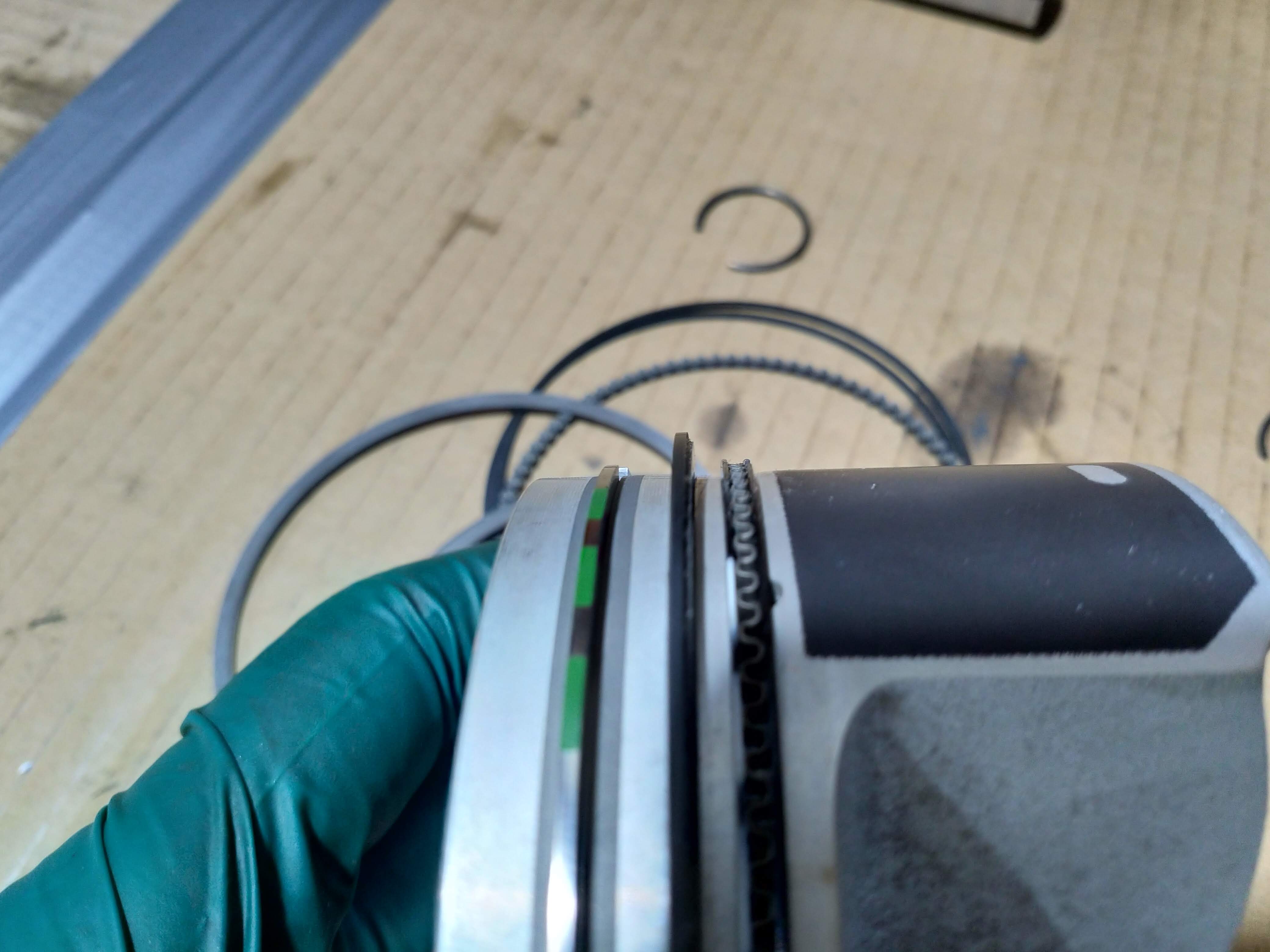
Next, i got the pistons on the rods, and fitted everything to Mahle and Arrow spec

All gudion pins facing upwards ( if you have them sideways, the up down force can cause the snap ring to squash and loose tension and fall out)
all rings fit 120 degrees apart with oil scrap gap 180 from scraper ring gaps
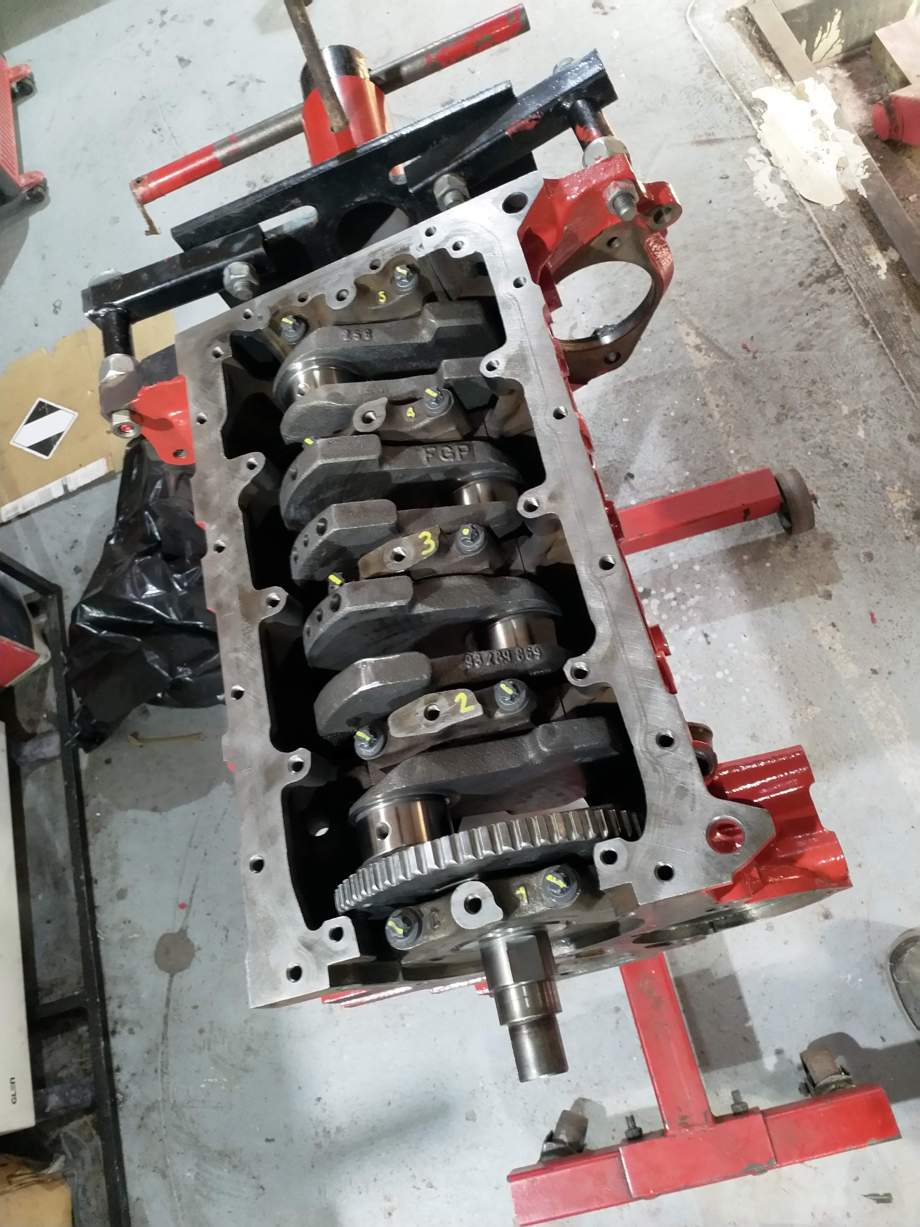
conrods fitted if the rod makes contact with the crank (which it never should!!!) the bearing 'stop notch' is against the cap, therefore it cannot physically spin a bearing.

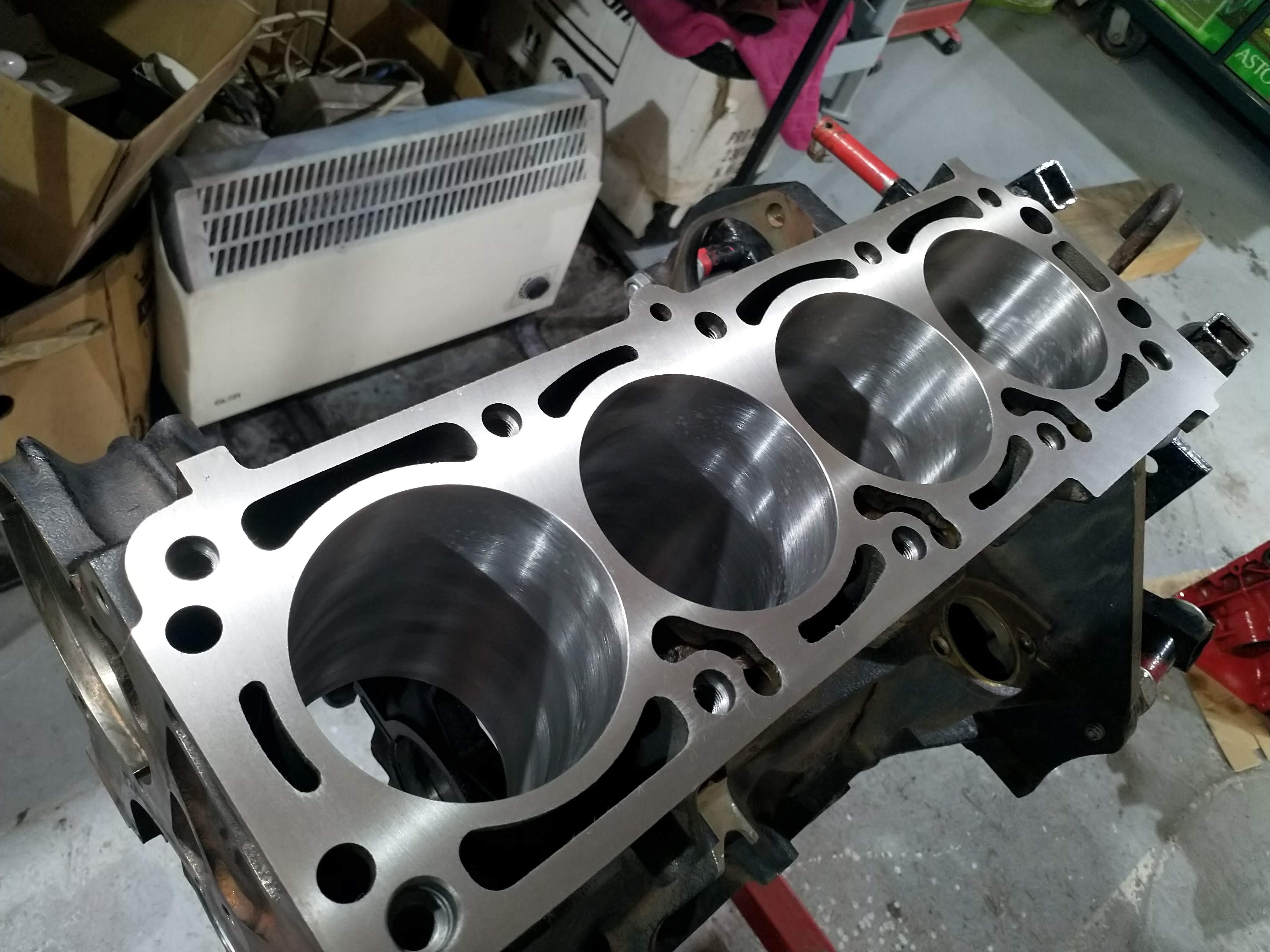
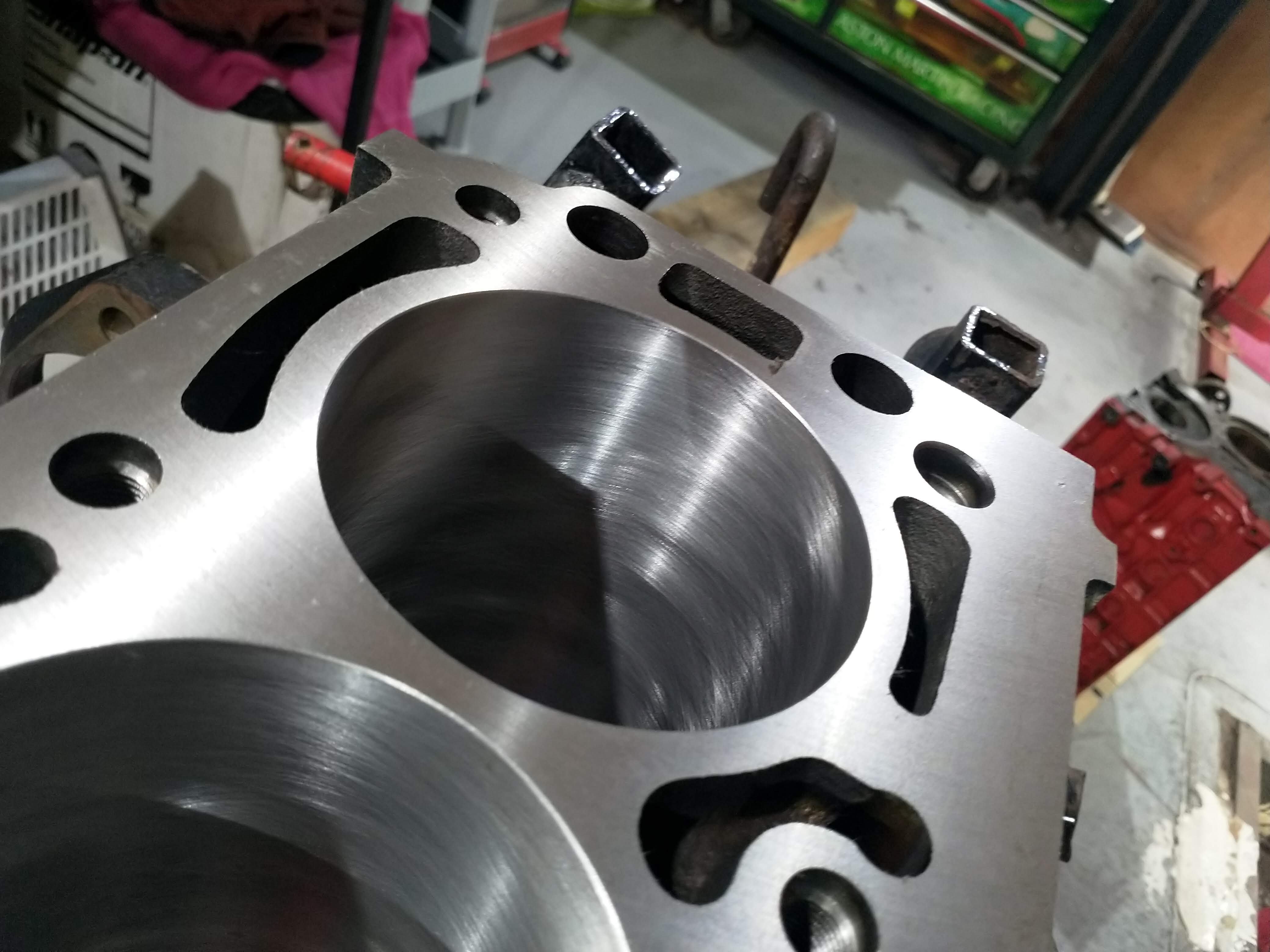
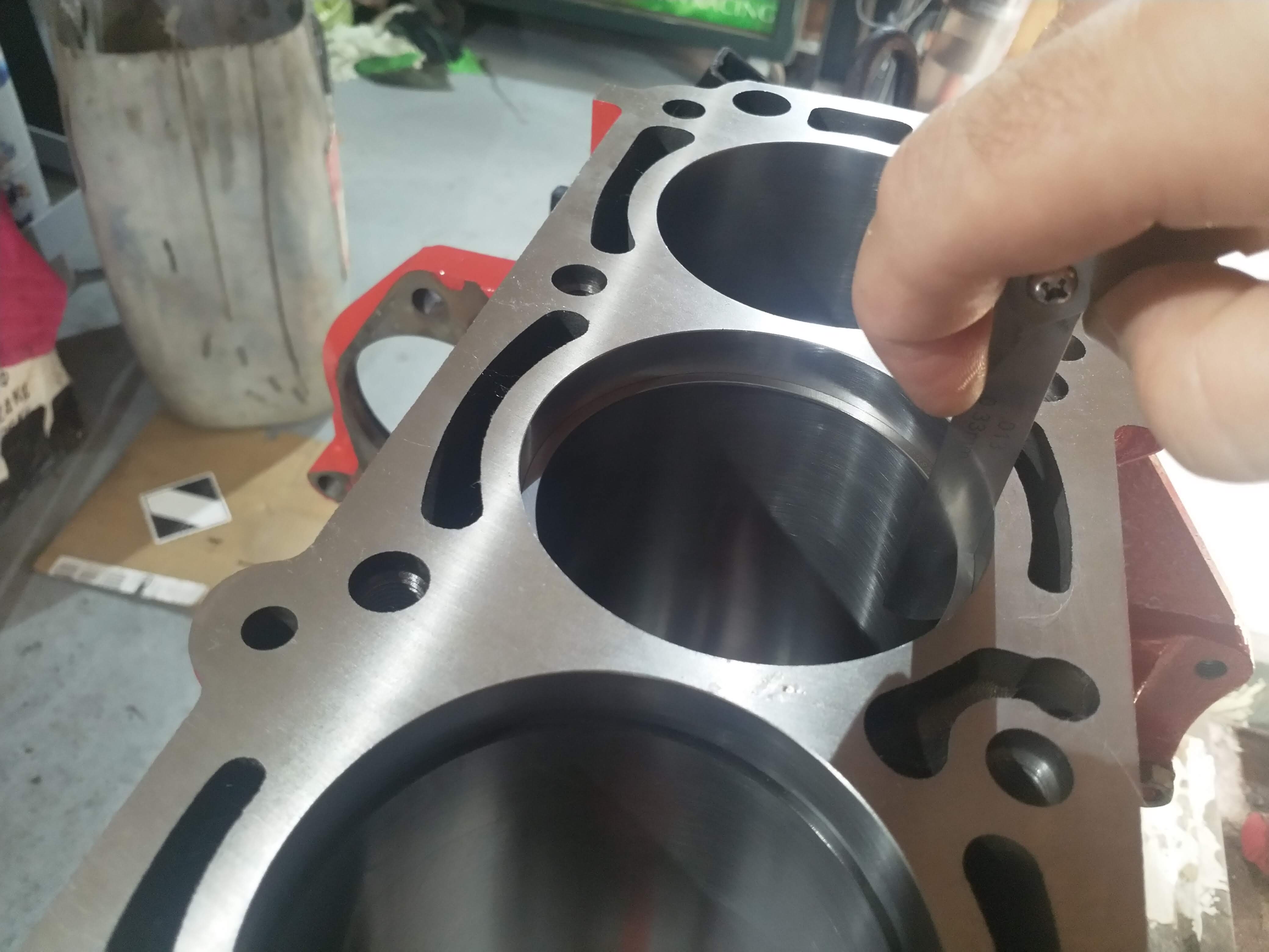
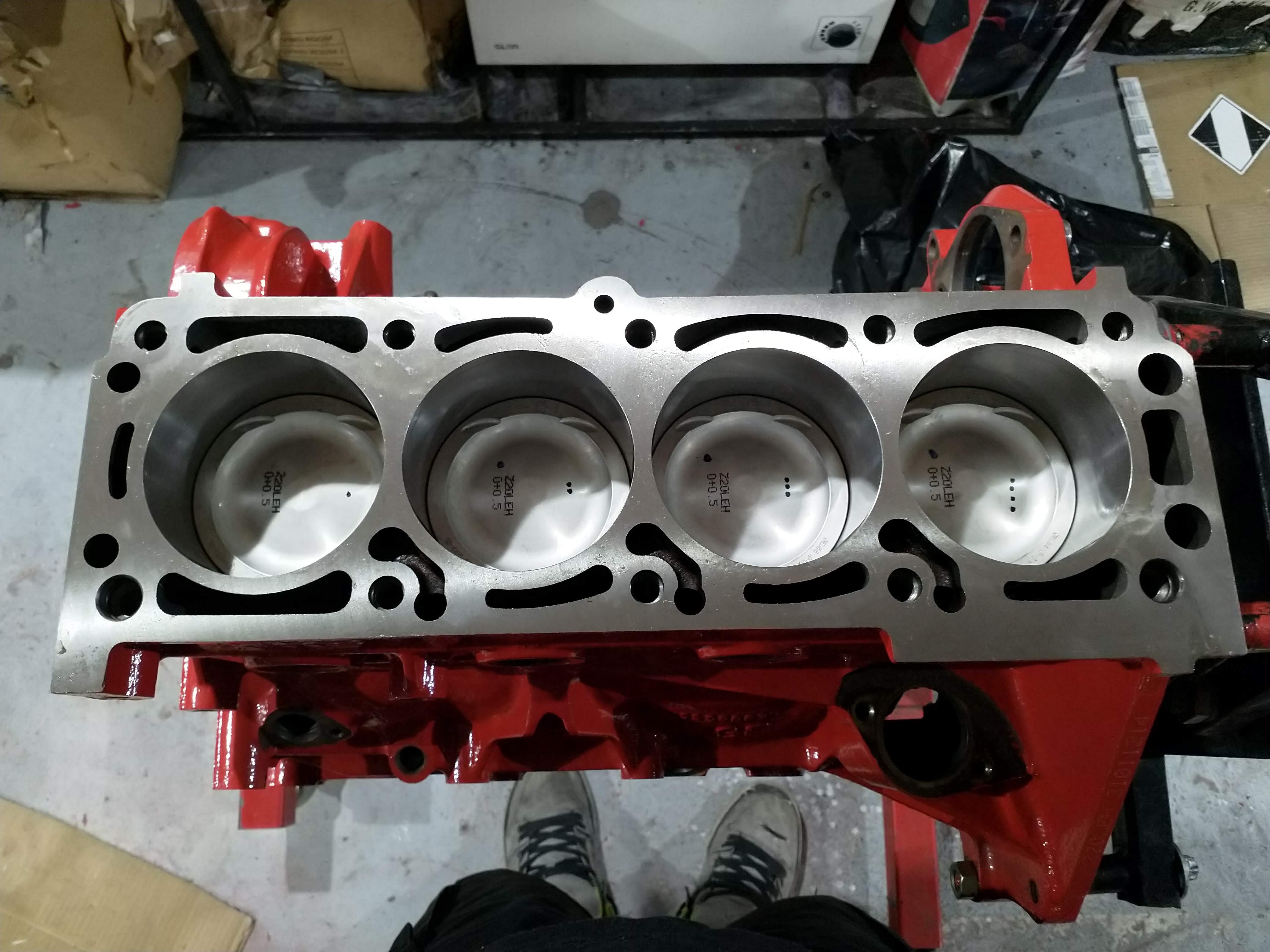
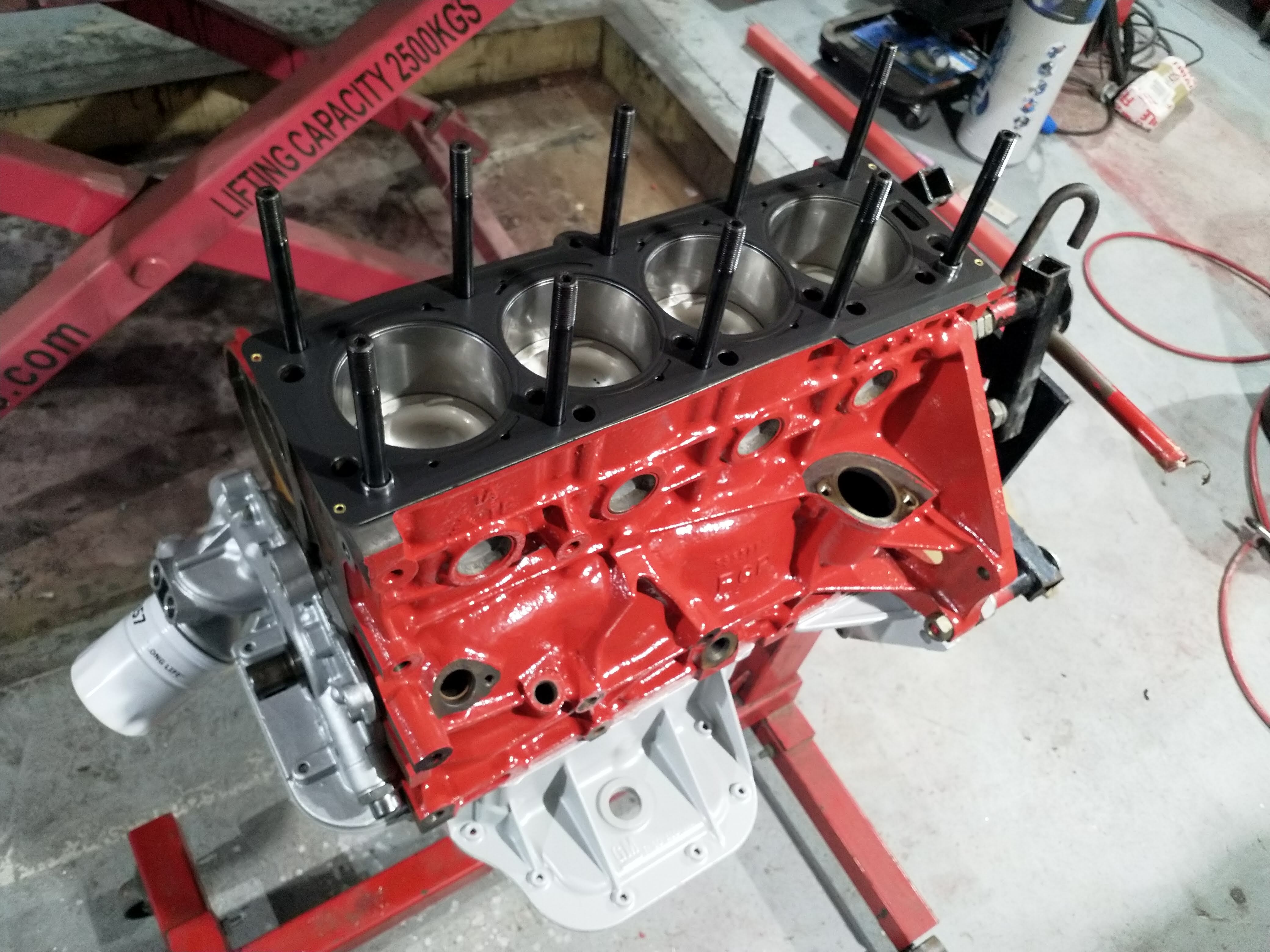
All pistons and rods chucked in the bores using a ring compressor, all went in very nicely actually!

full


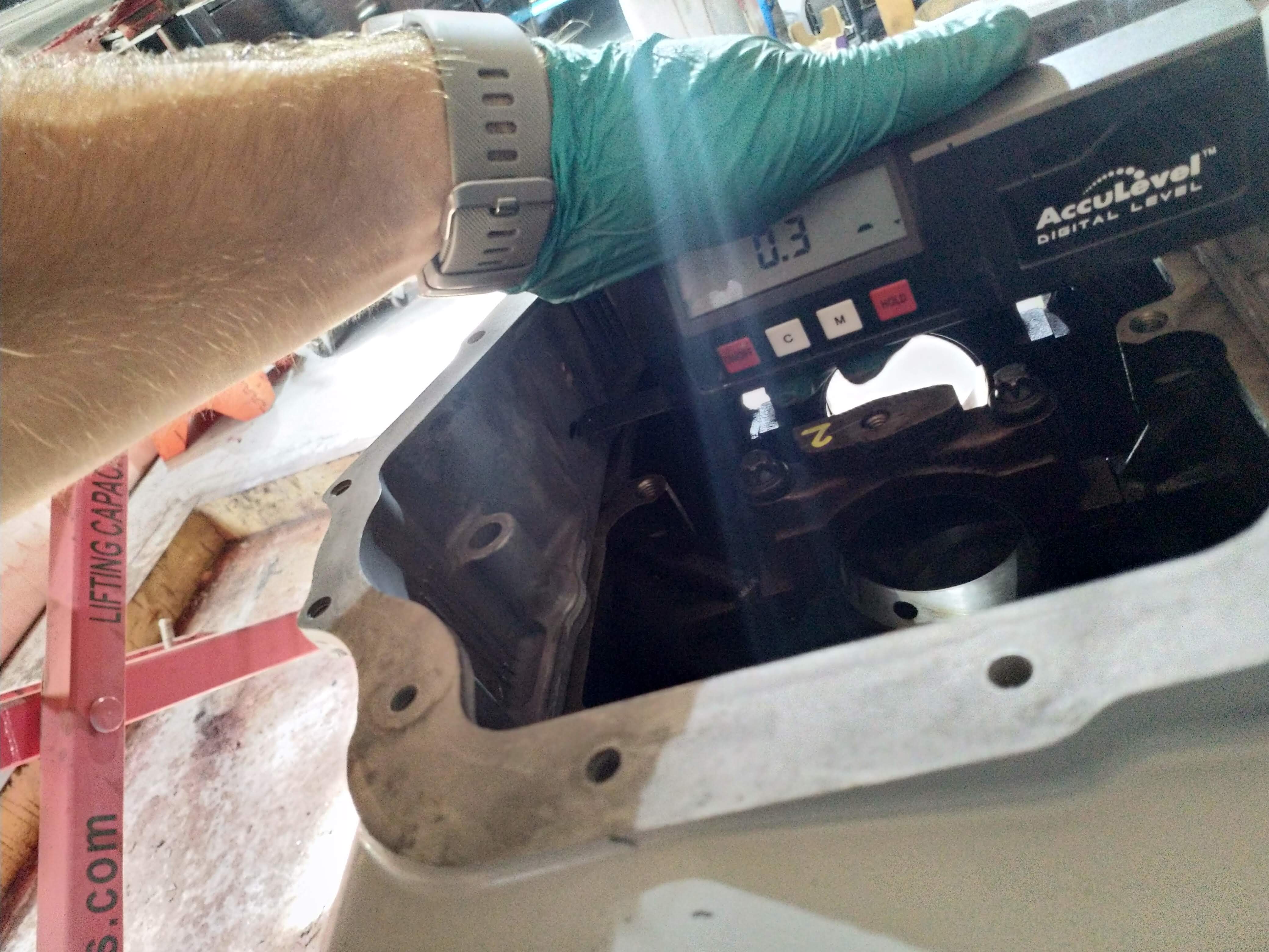
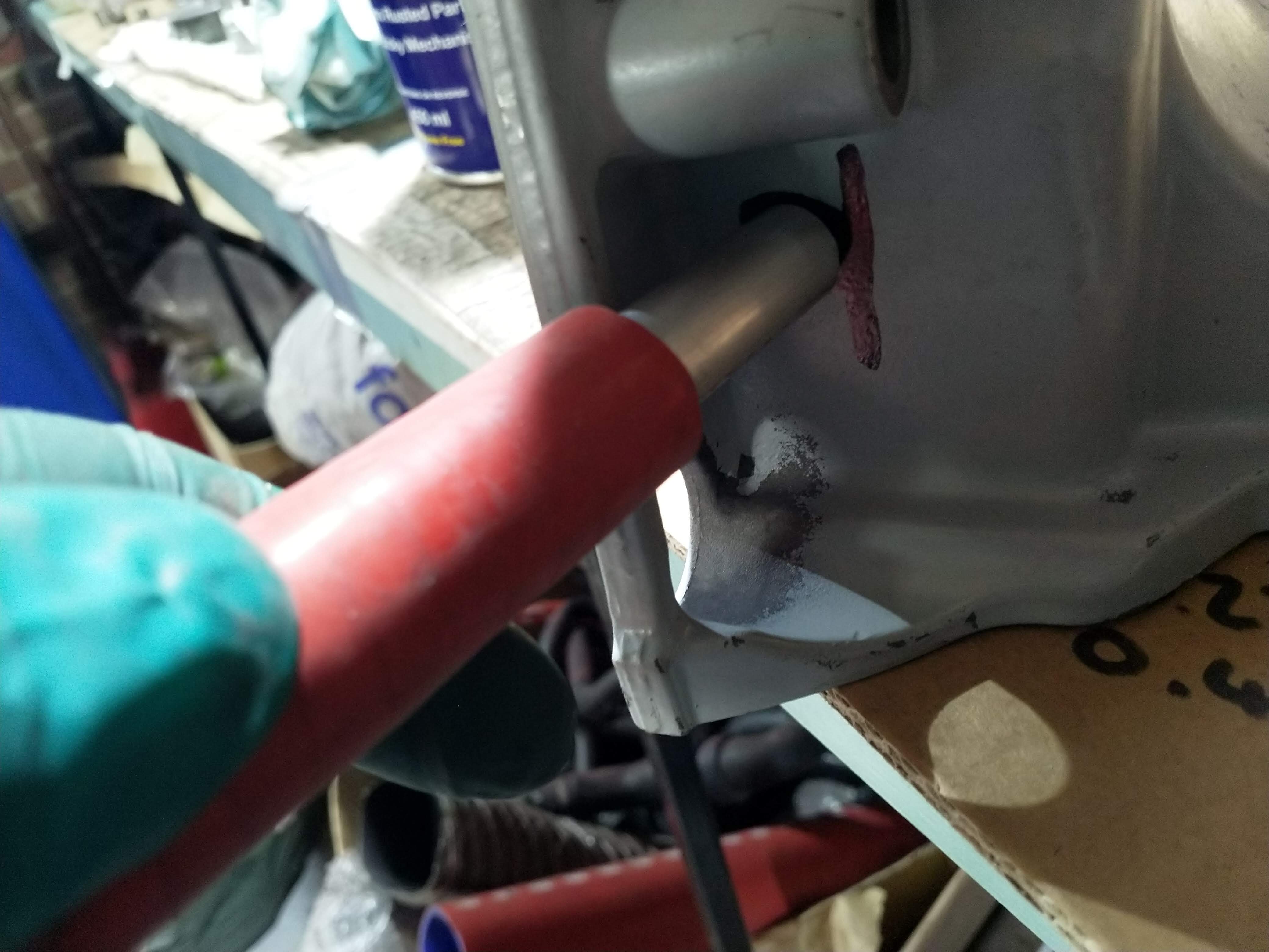
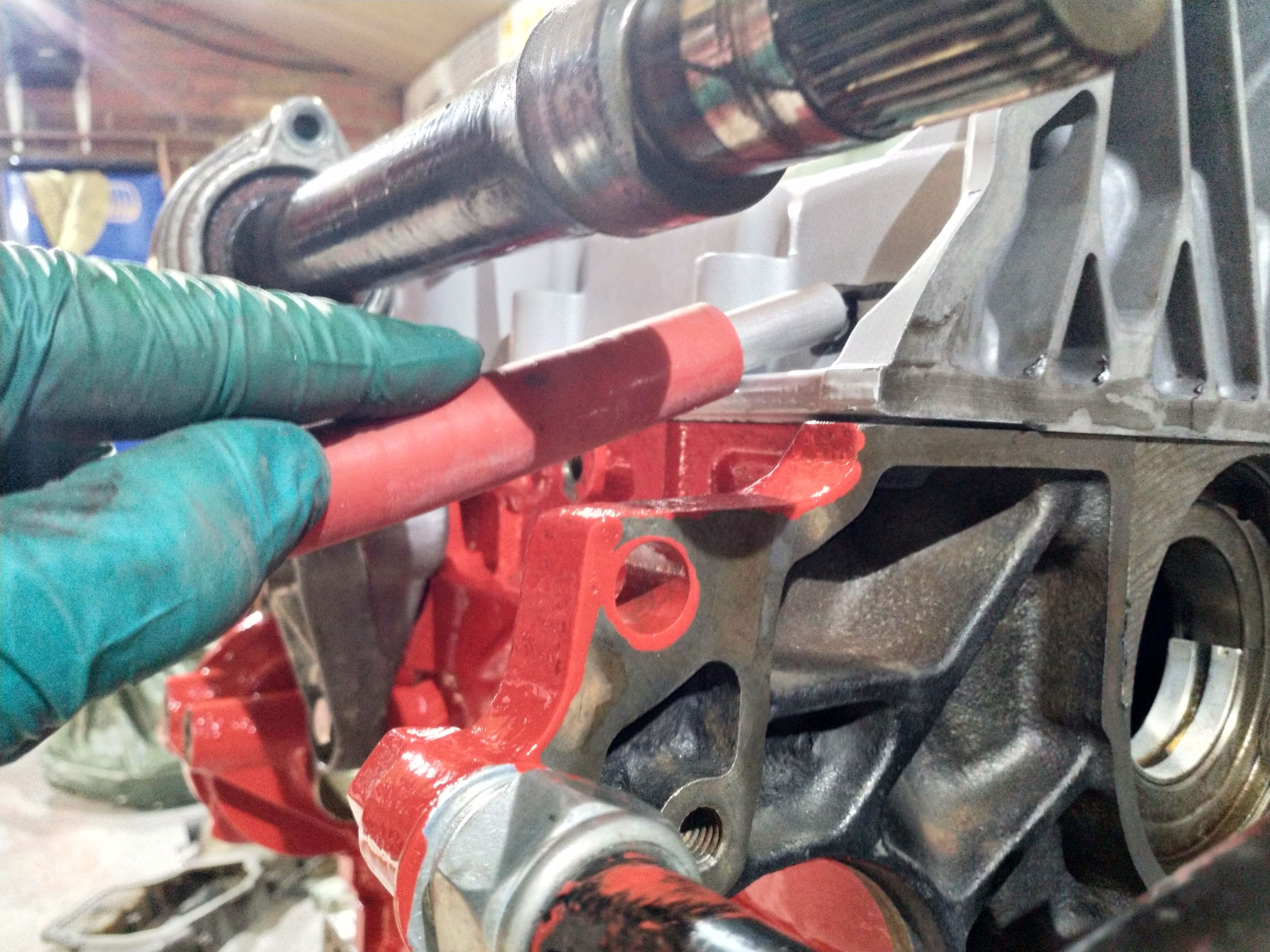
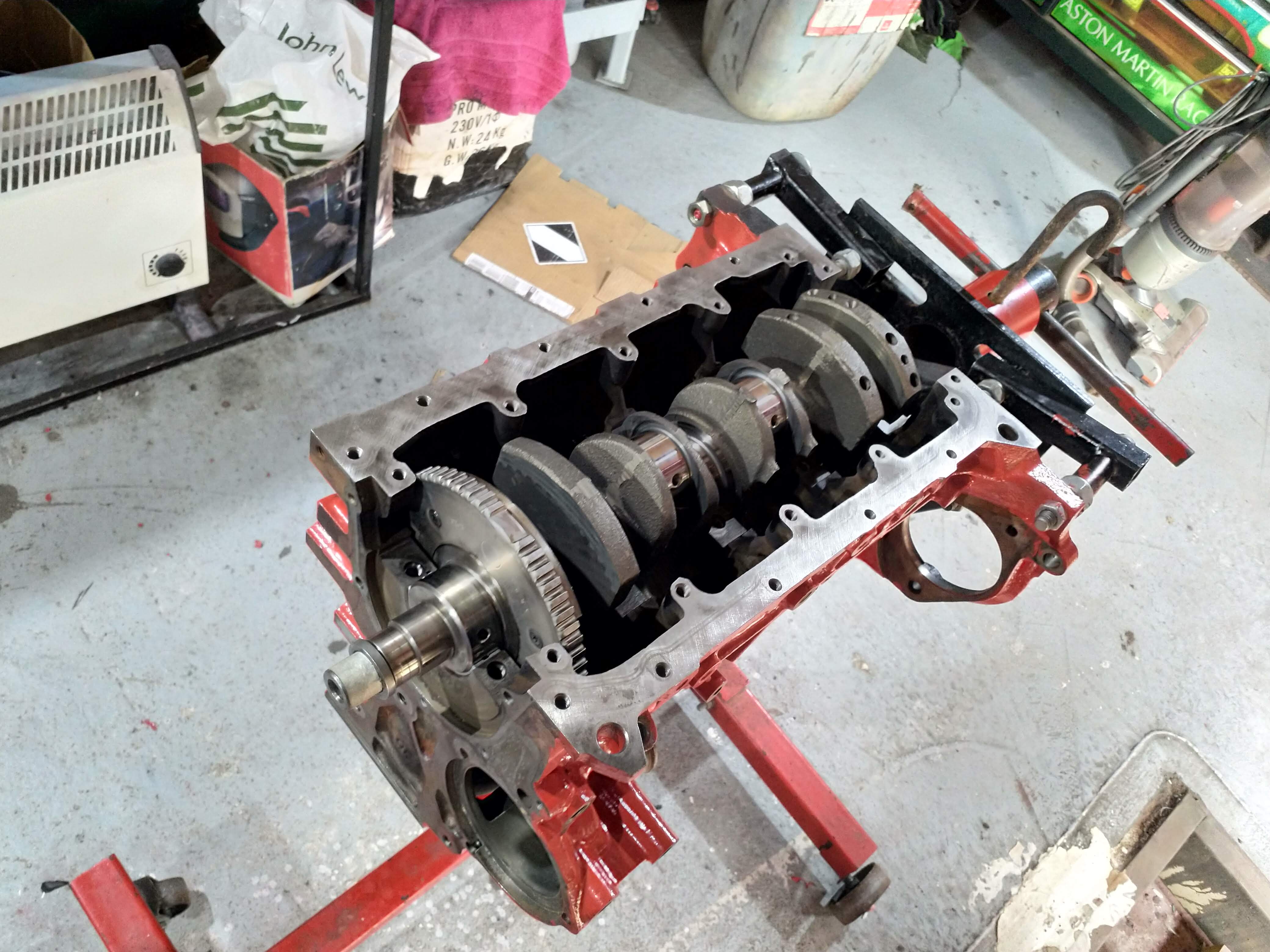
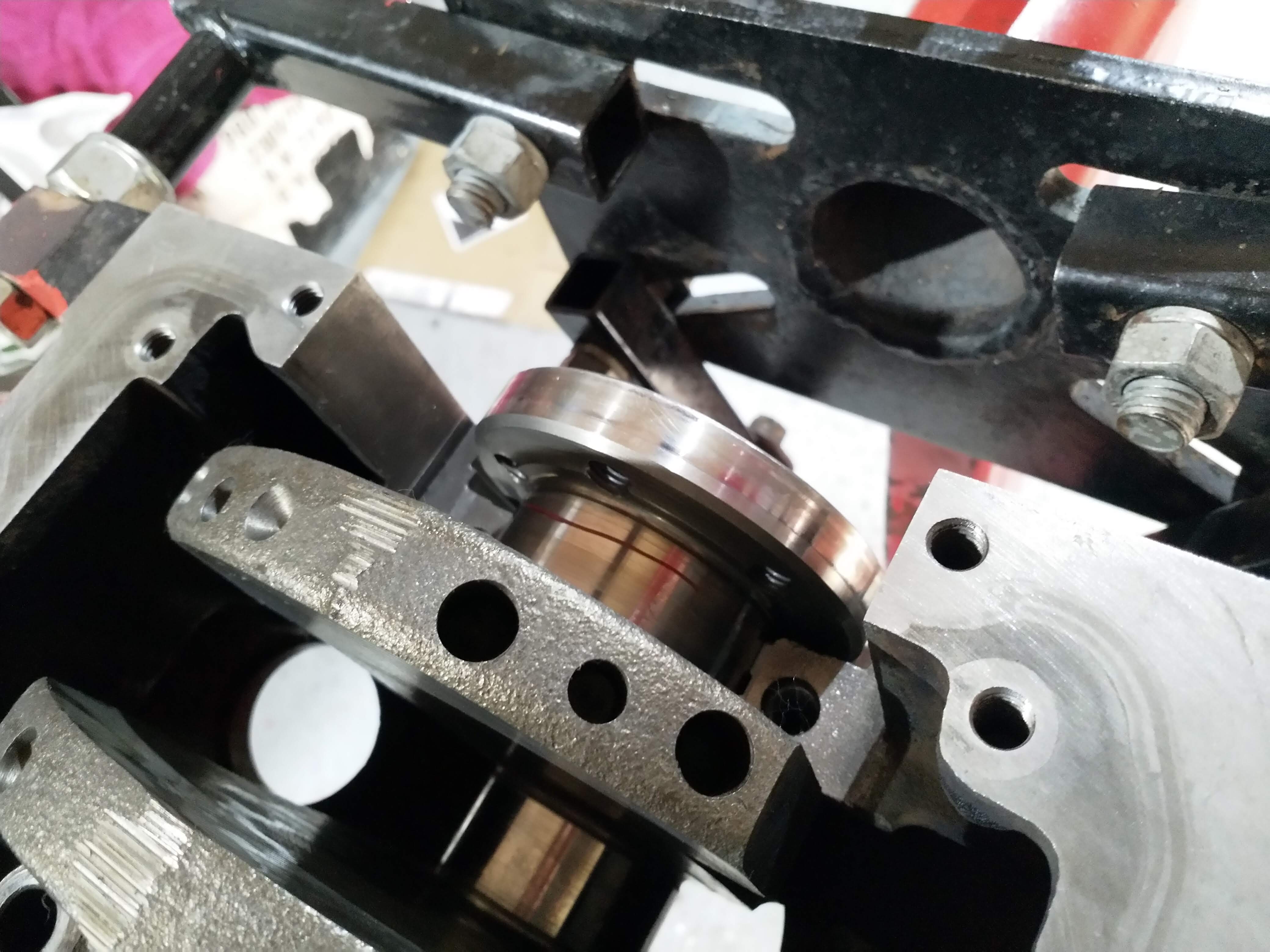
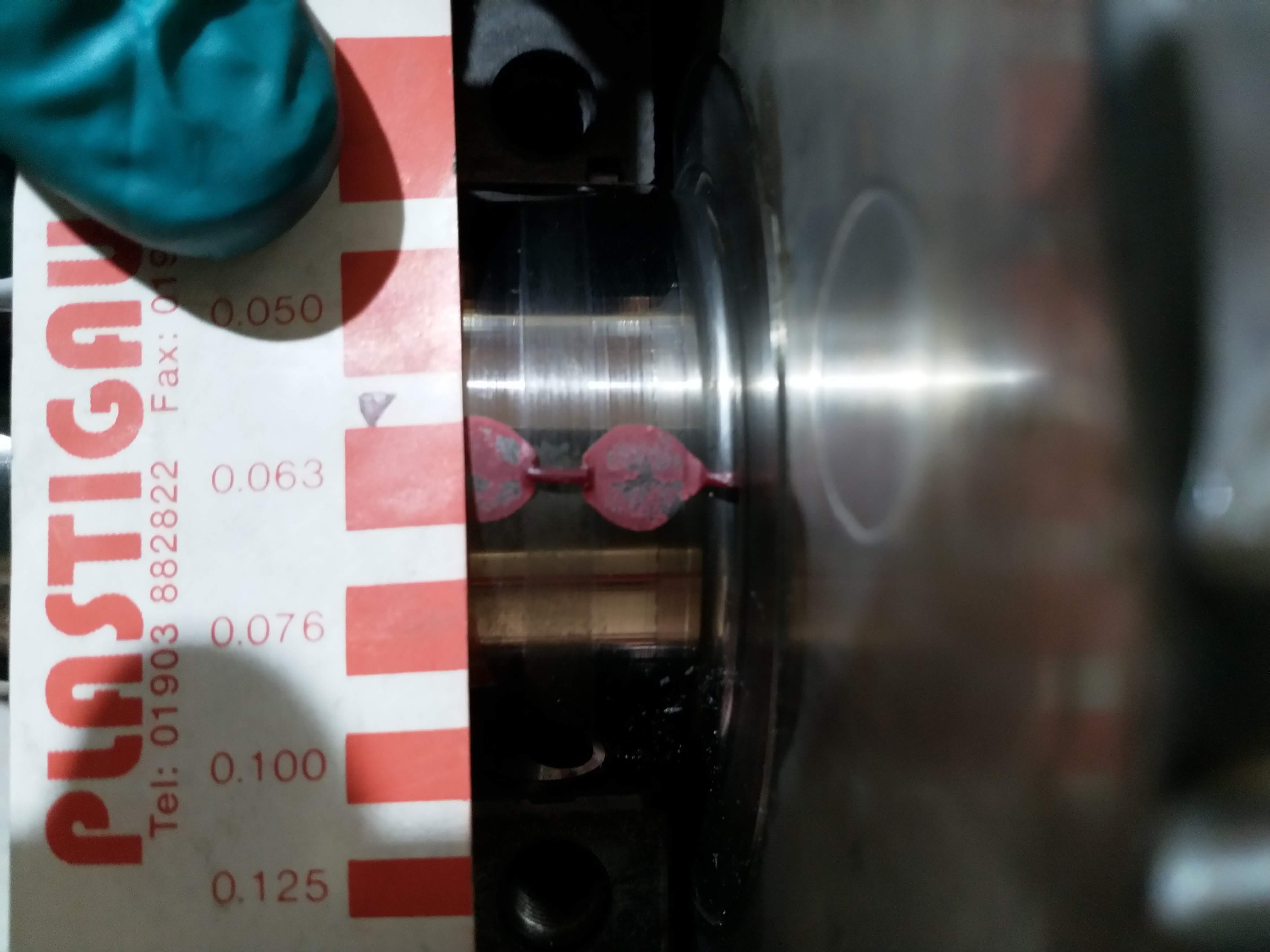
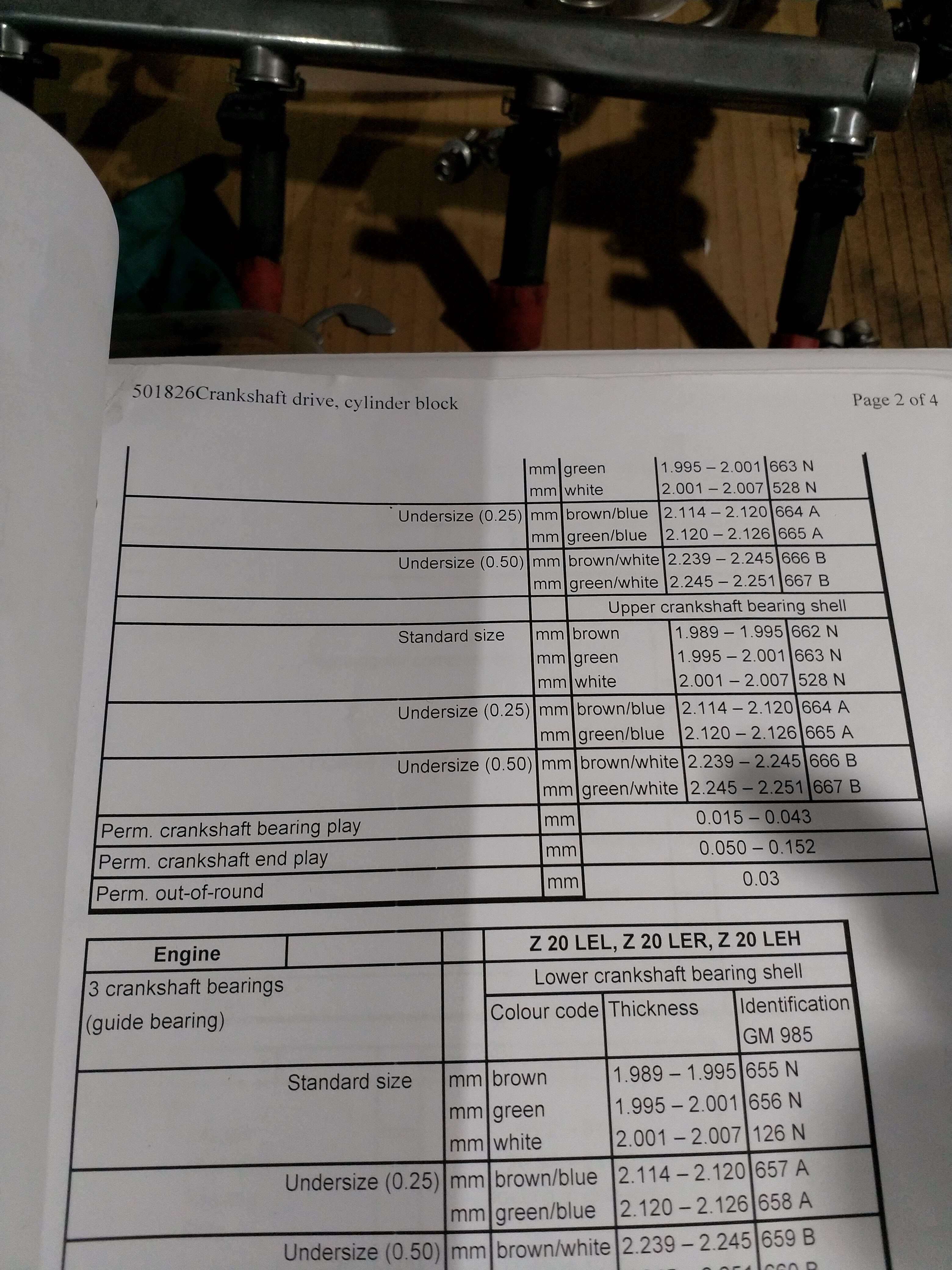
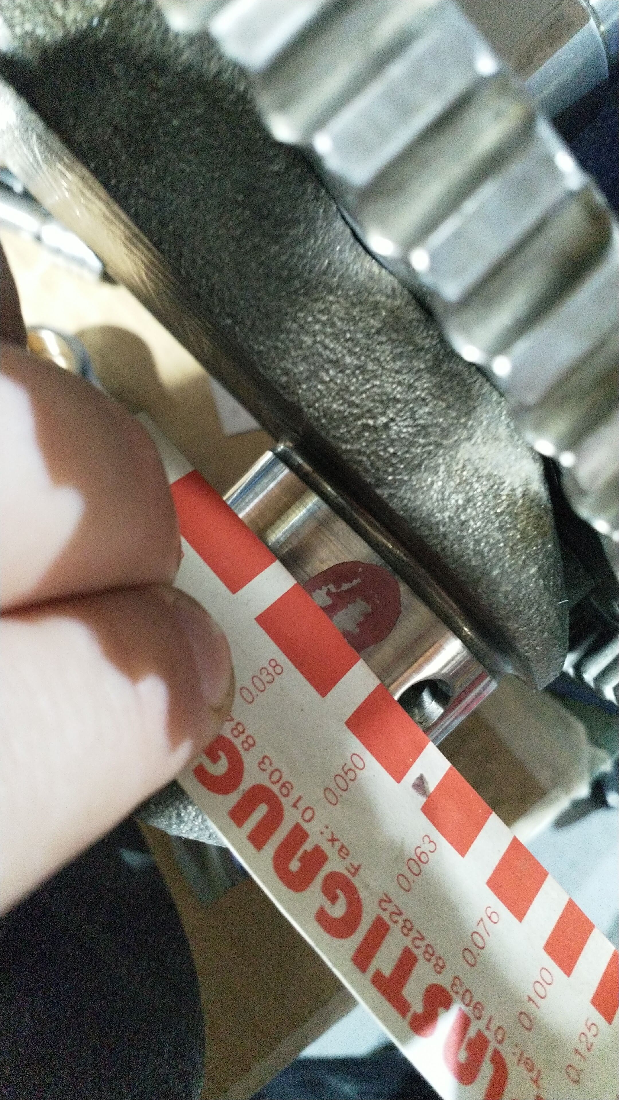
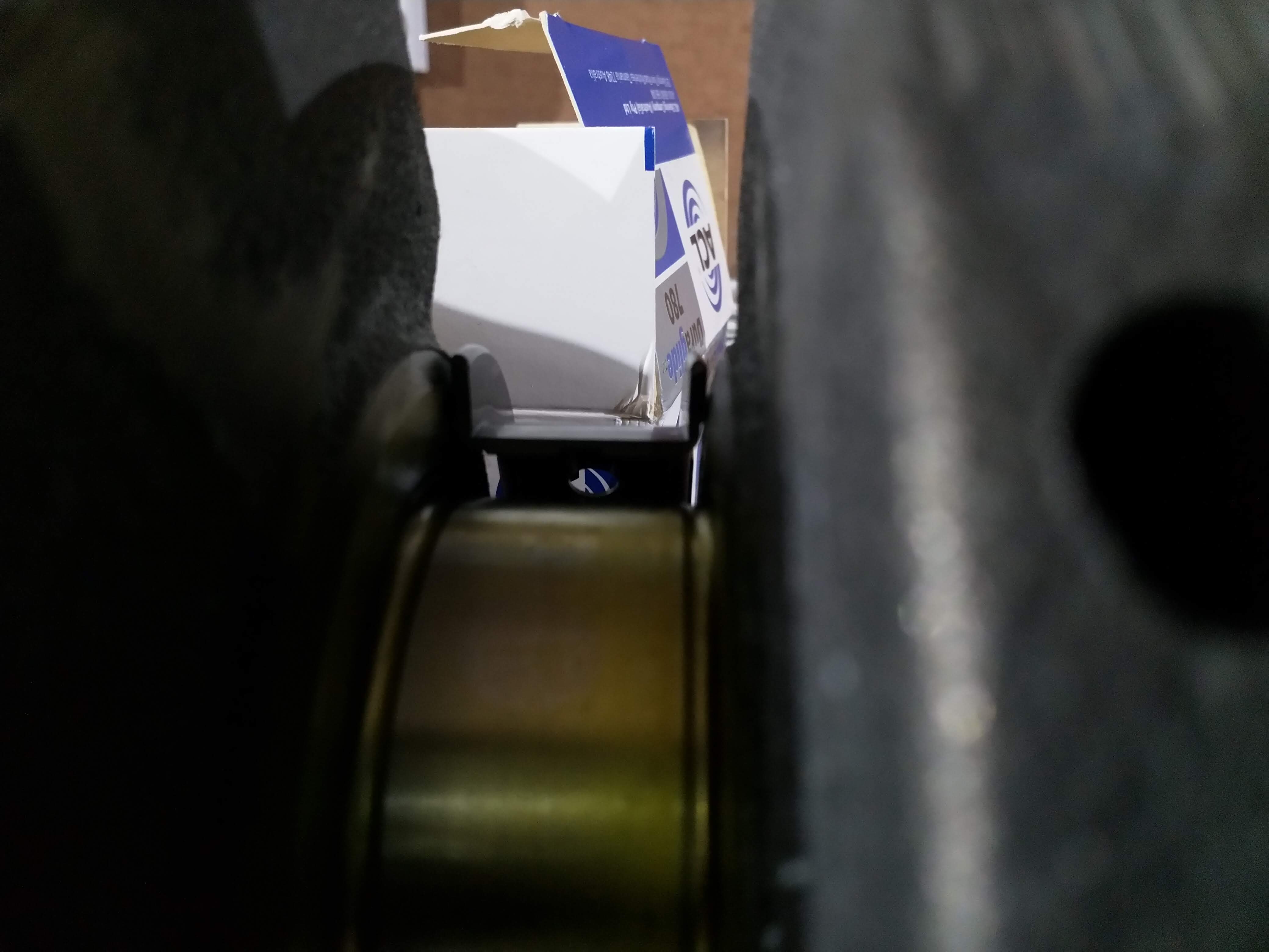
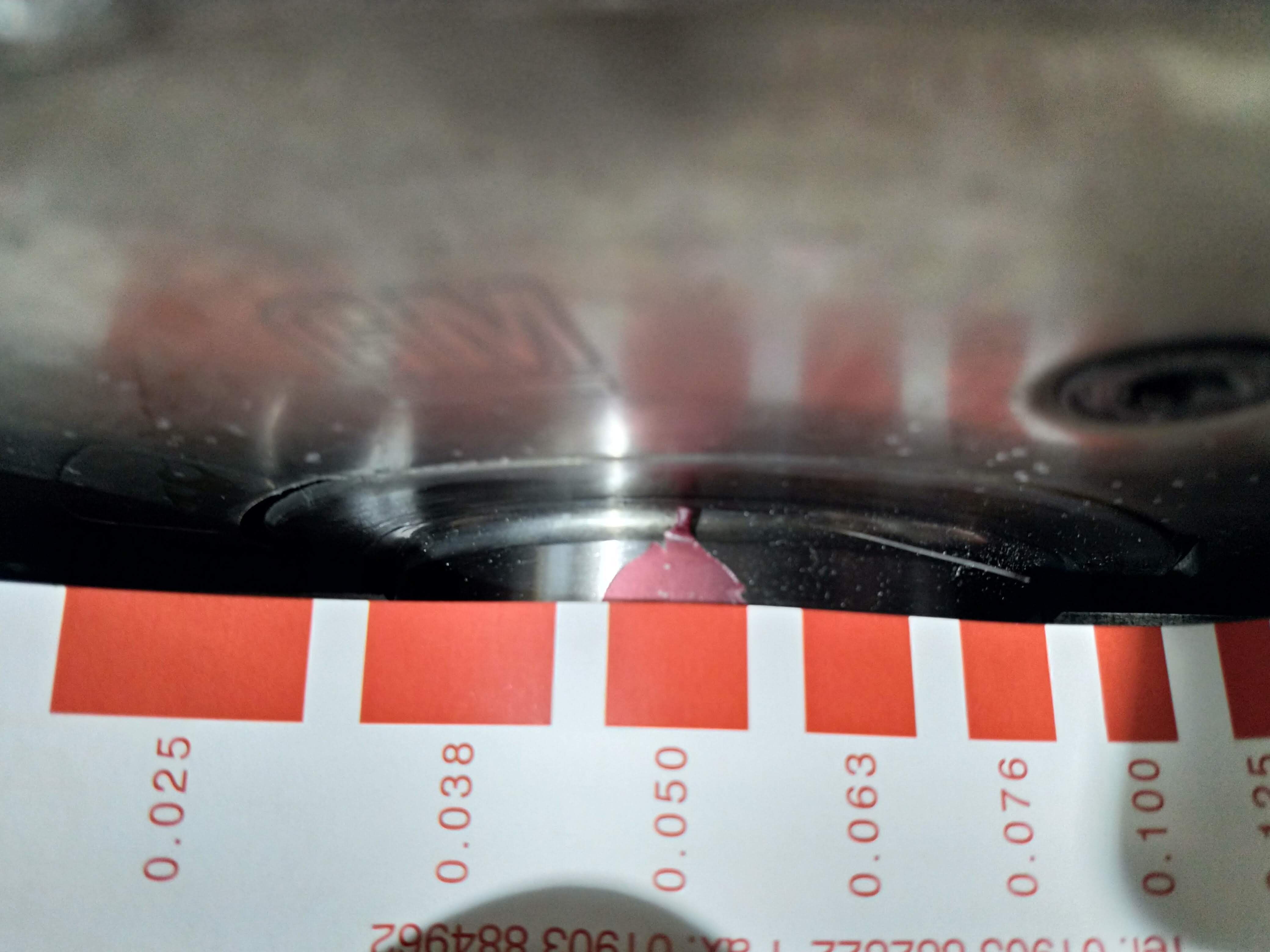
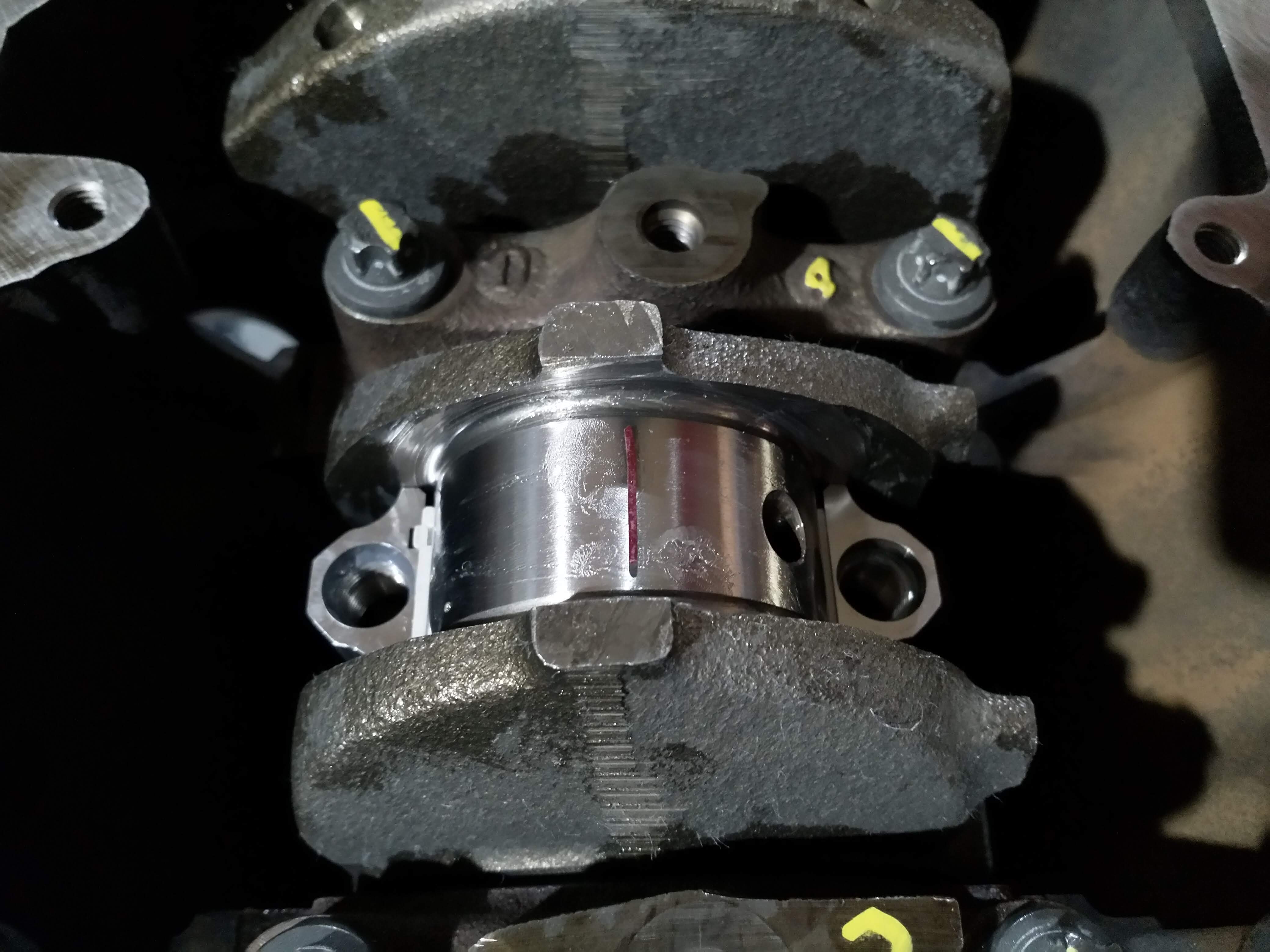
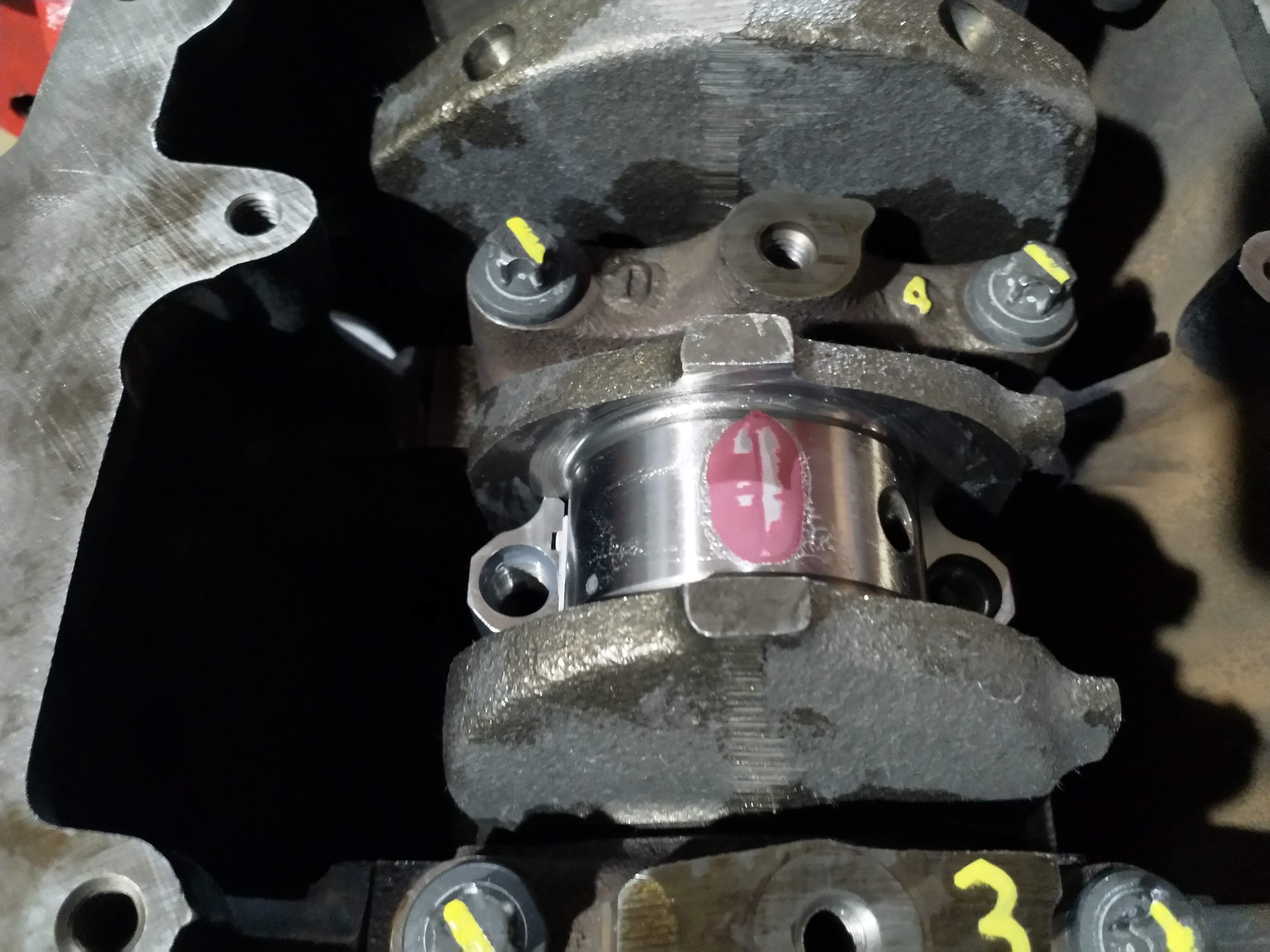
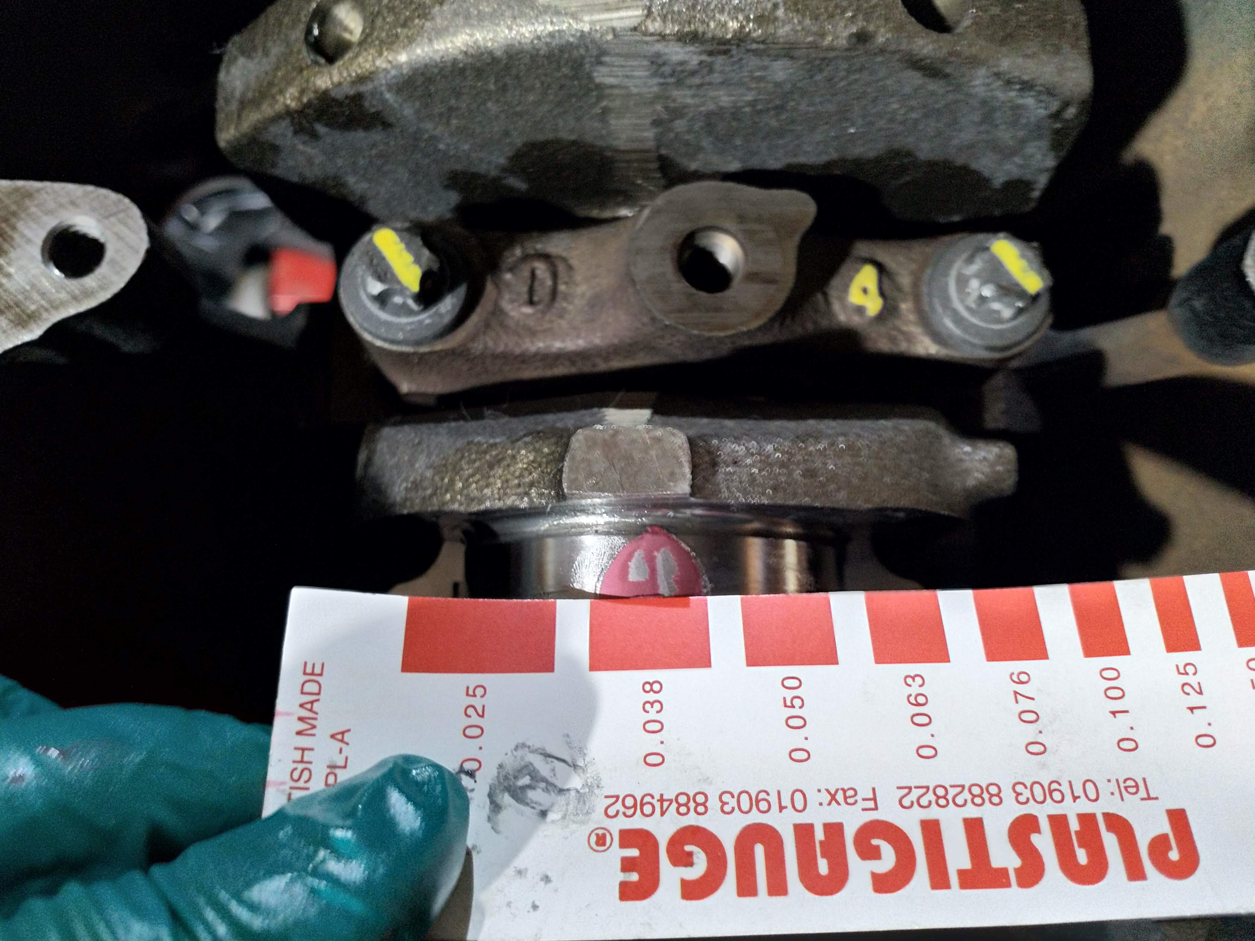
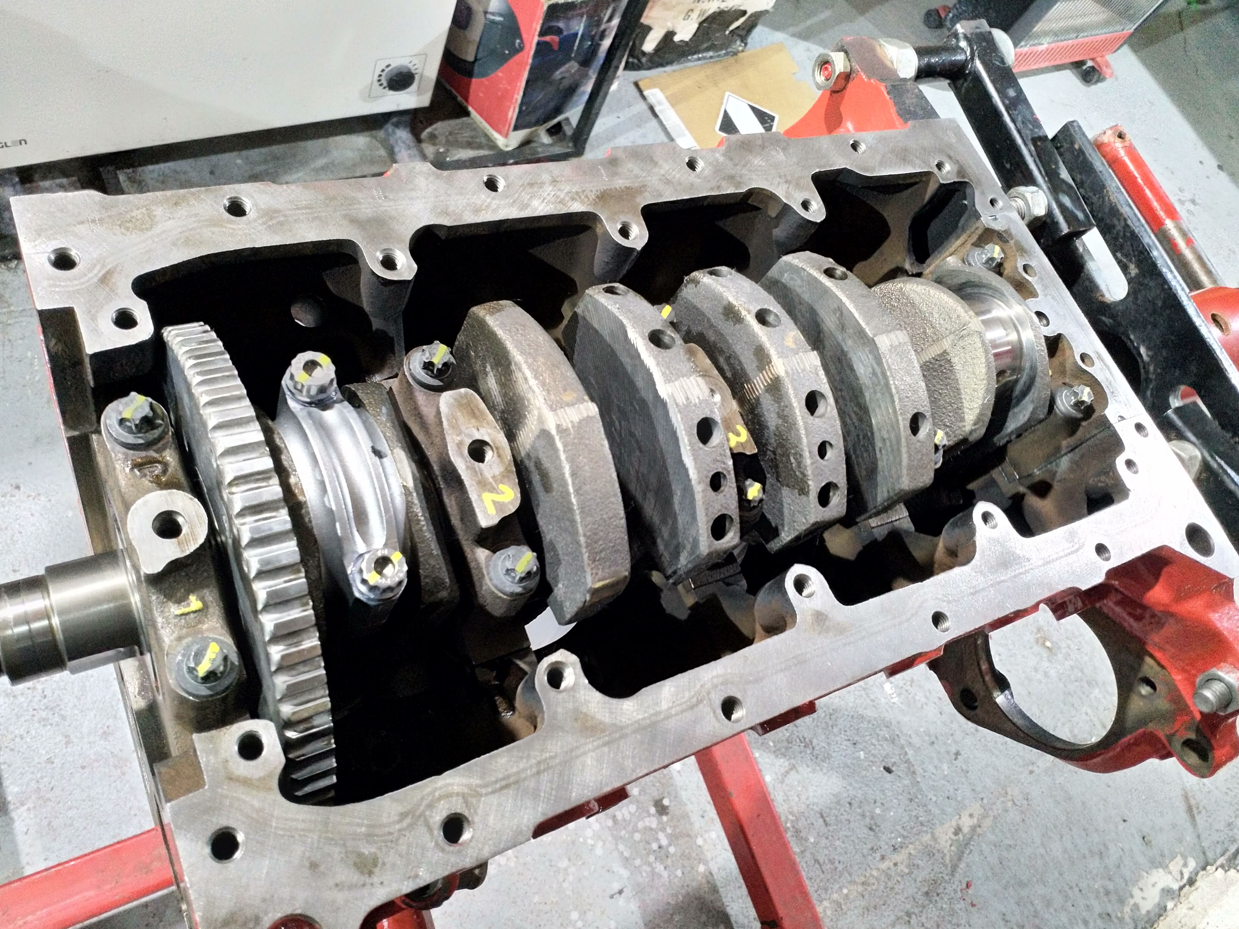
So next I plastigauged the Bigend. I know this seems backward to do it when everything is installed, But if you have measured everything as I have, I basically 'know' (:lol:) this is going to be fine! Also its also easier to keep everything stationary like this and not 'smudge' the plastigauge.

full

full

full


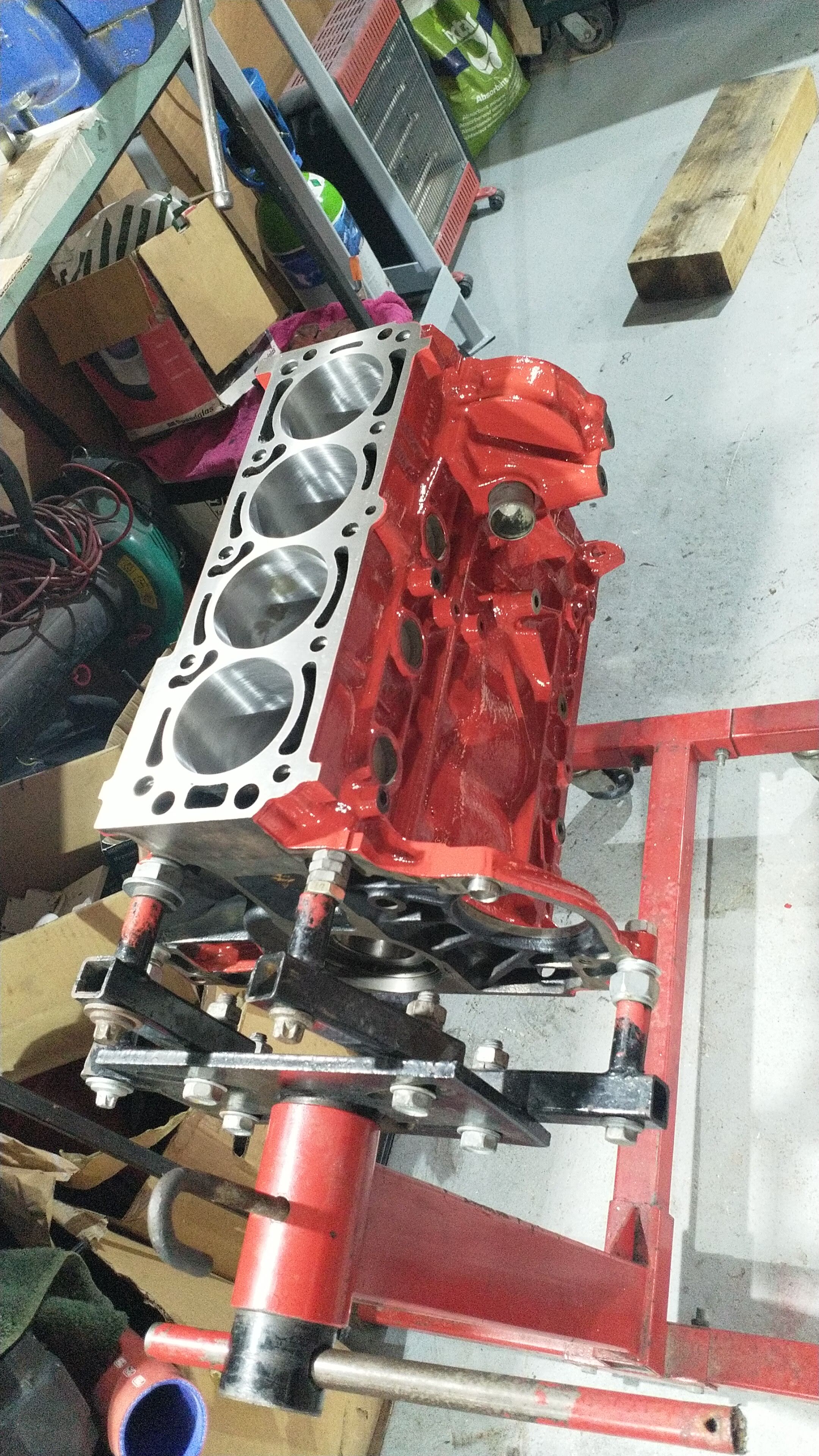
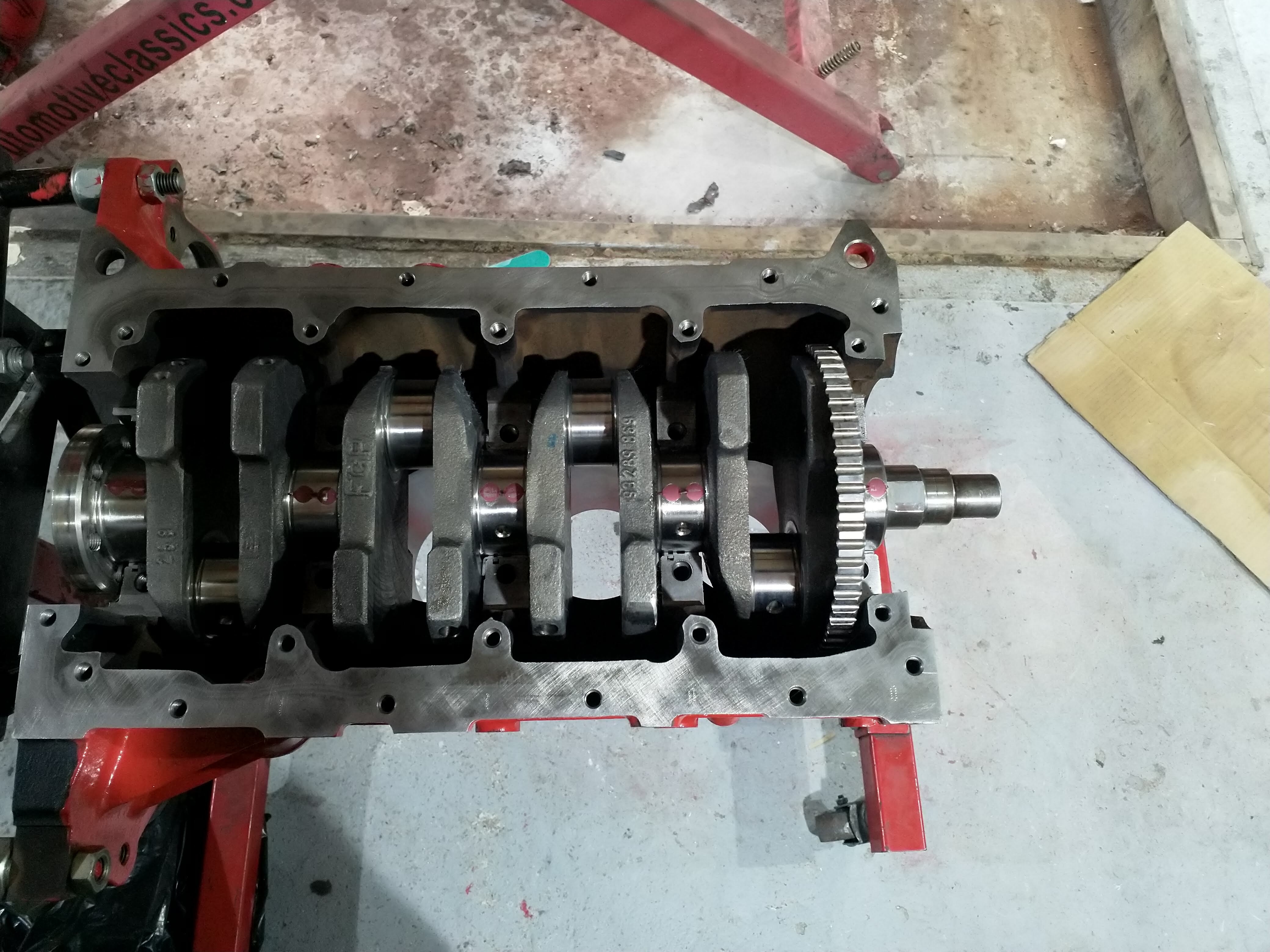
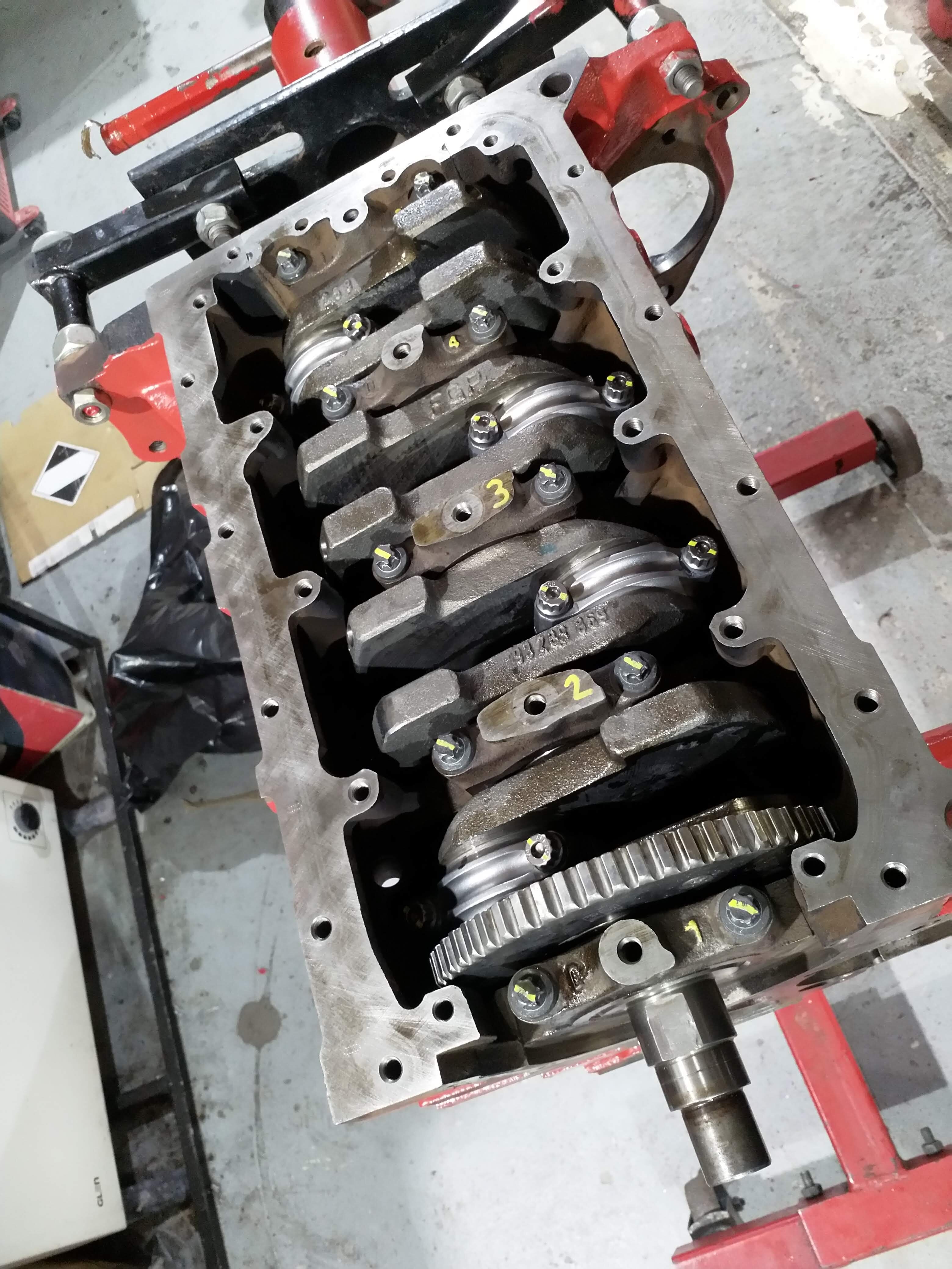
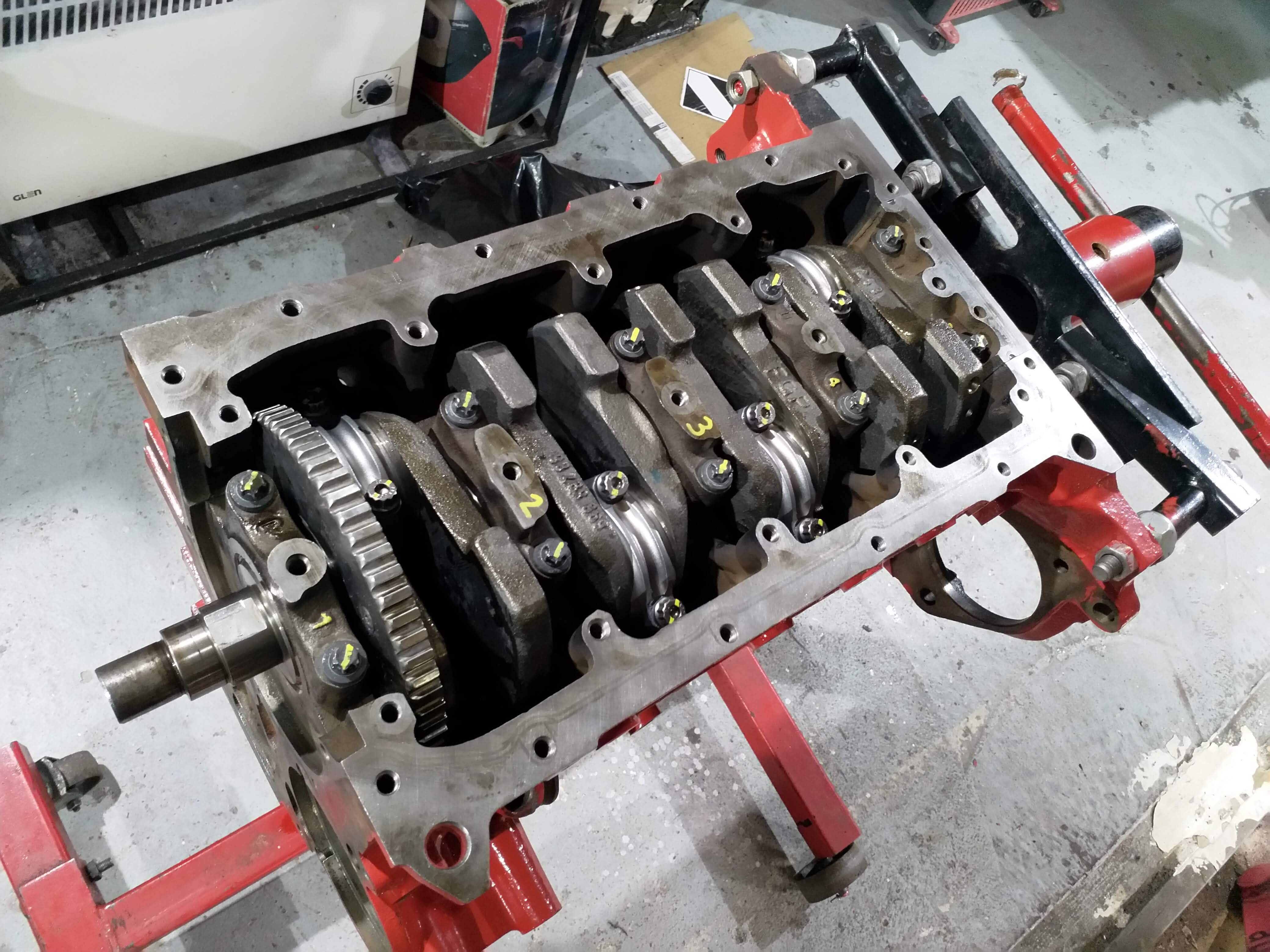
Everything checks out spot on. Checked all 4, all good so cleaned up, smear of thick oil and rod caps on and torqued down. sexy

full

full

full


Lovely,
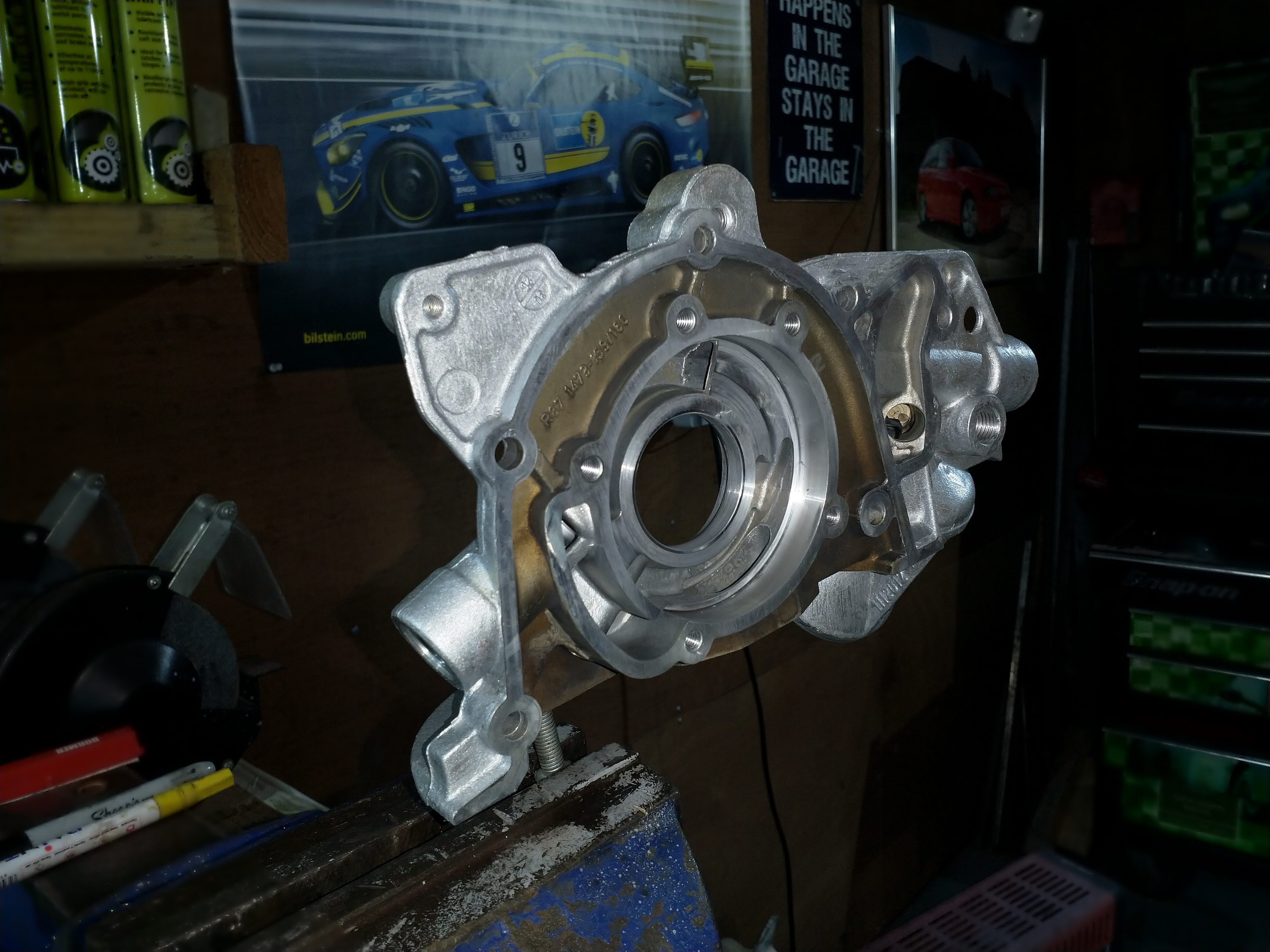
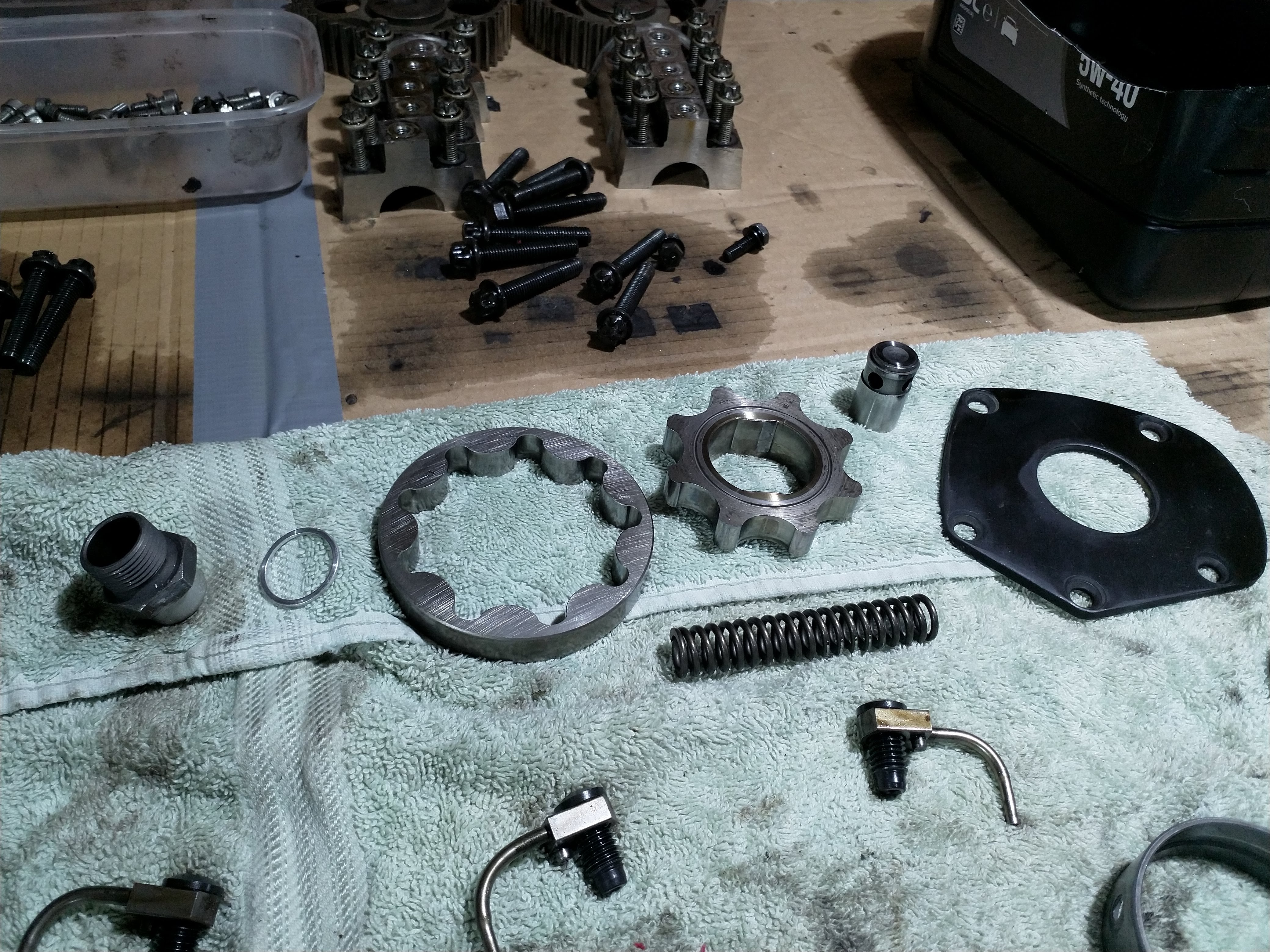
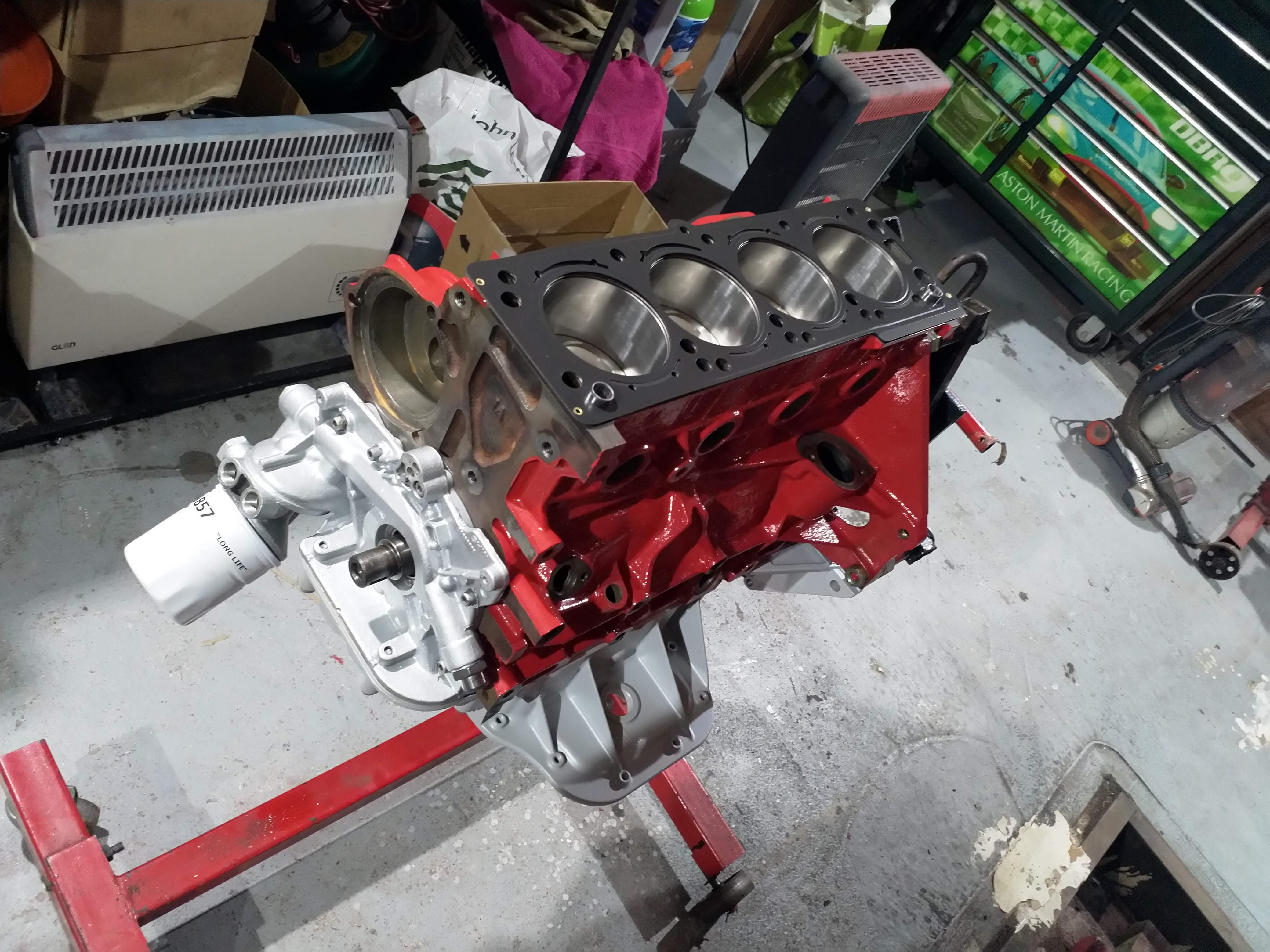
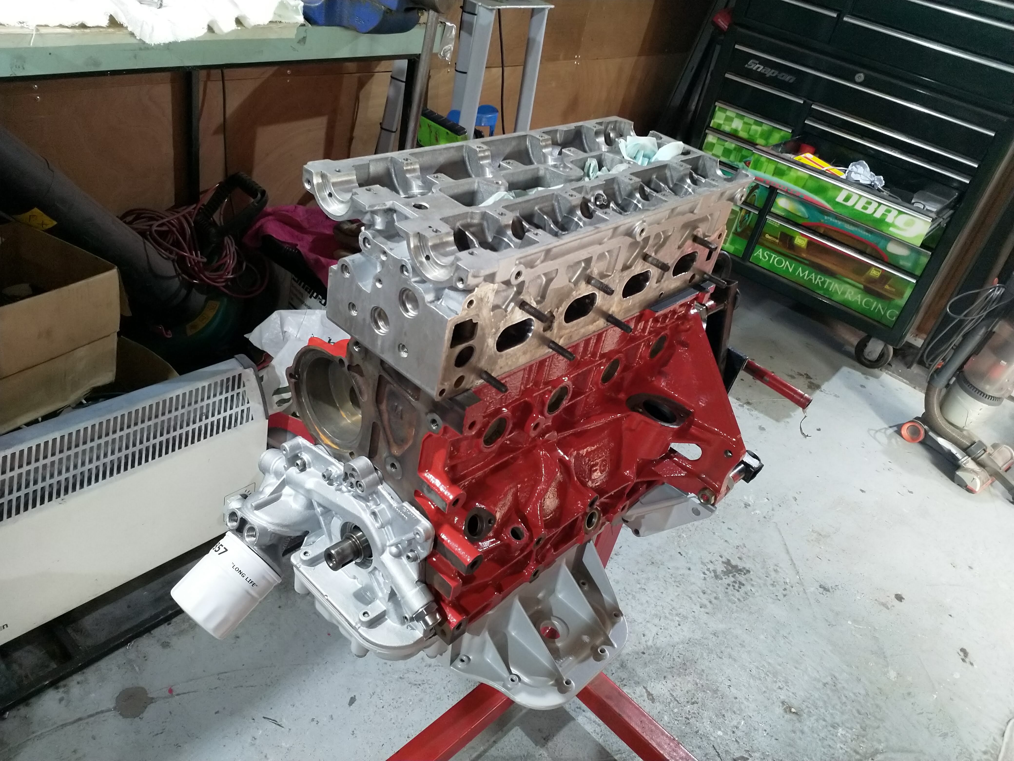
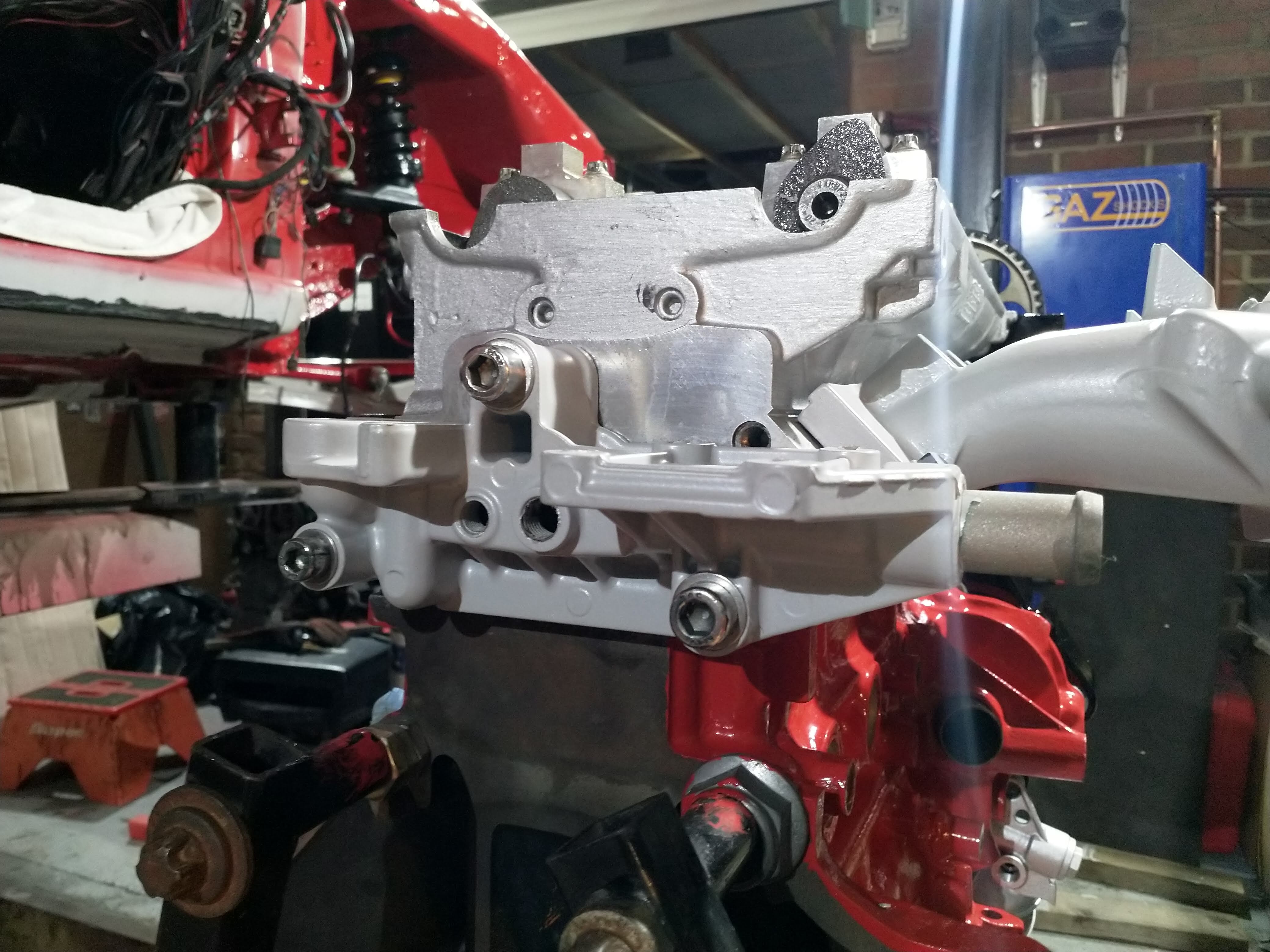
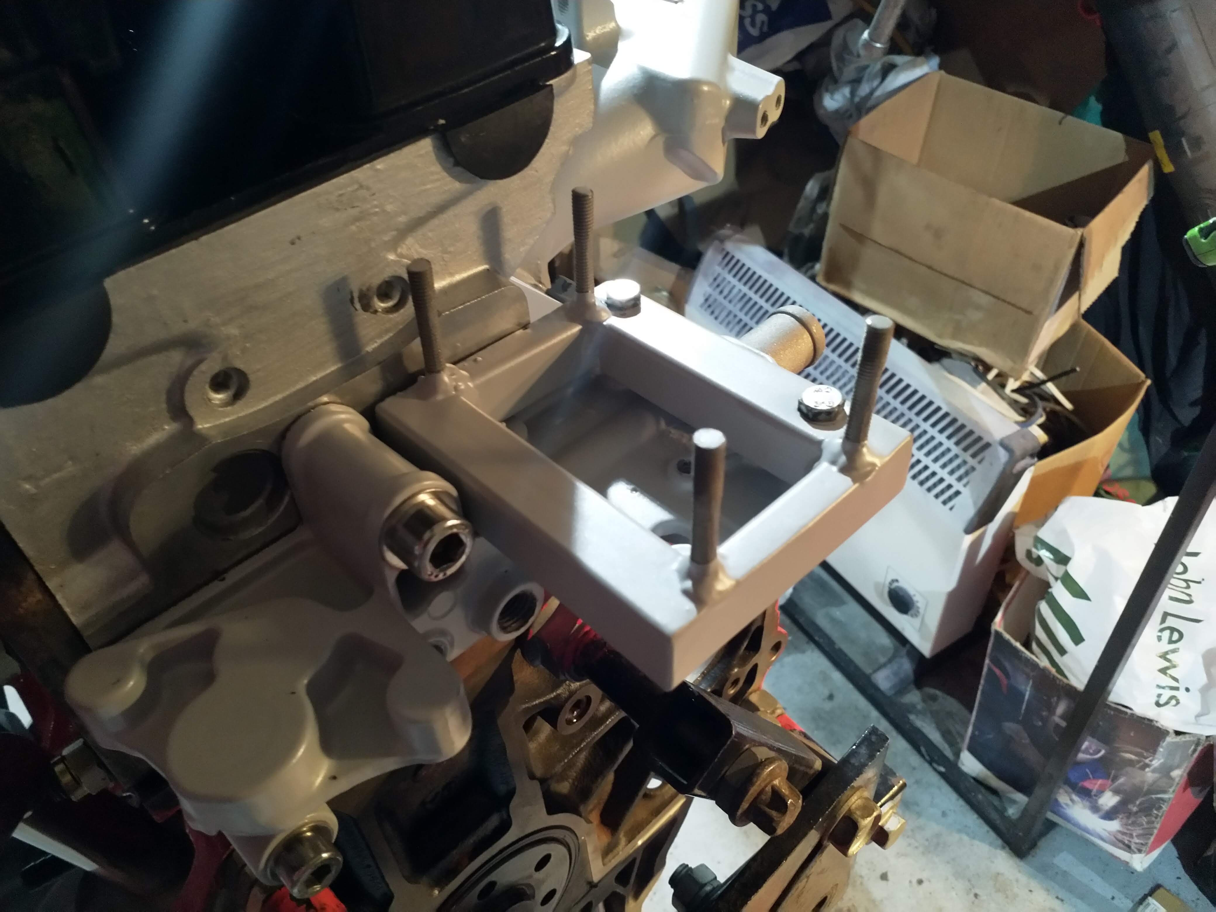
Headgasket on, new head dowels, new oil pump dowels, Oil pump on.

full


Arp head studs in. I've always wanted to run these!
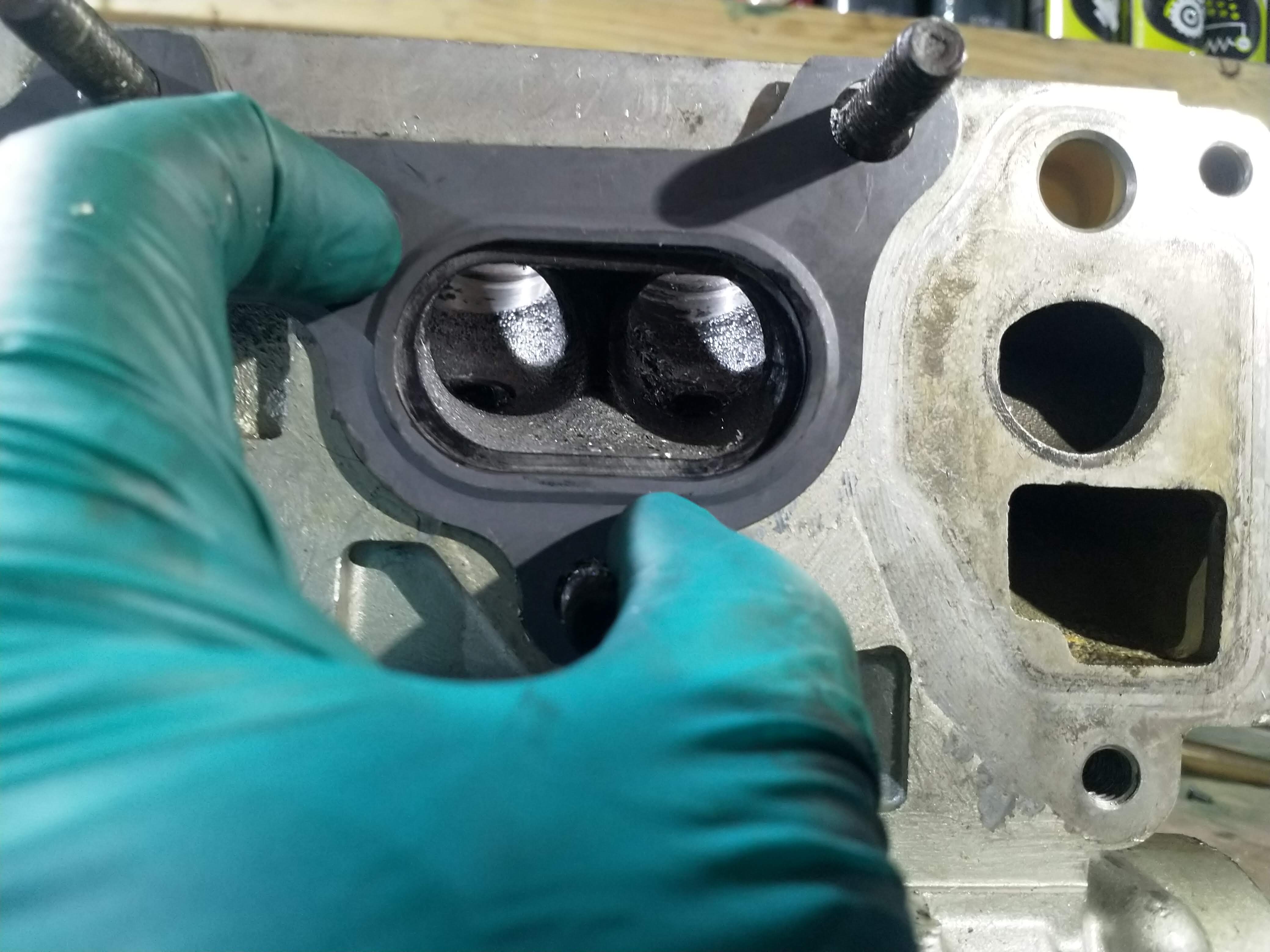
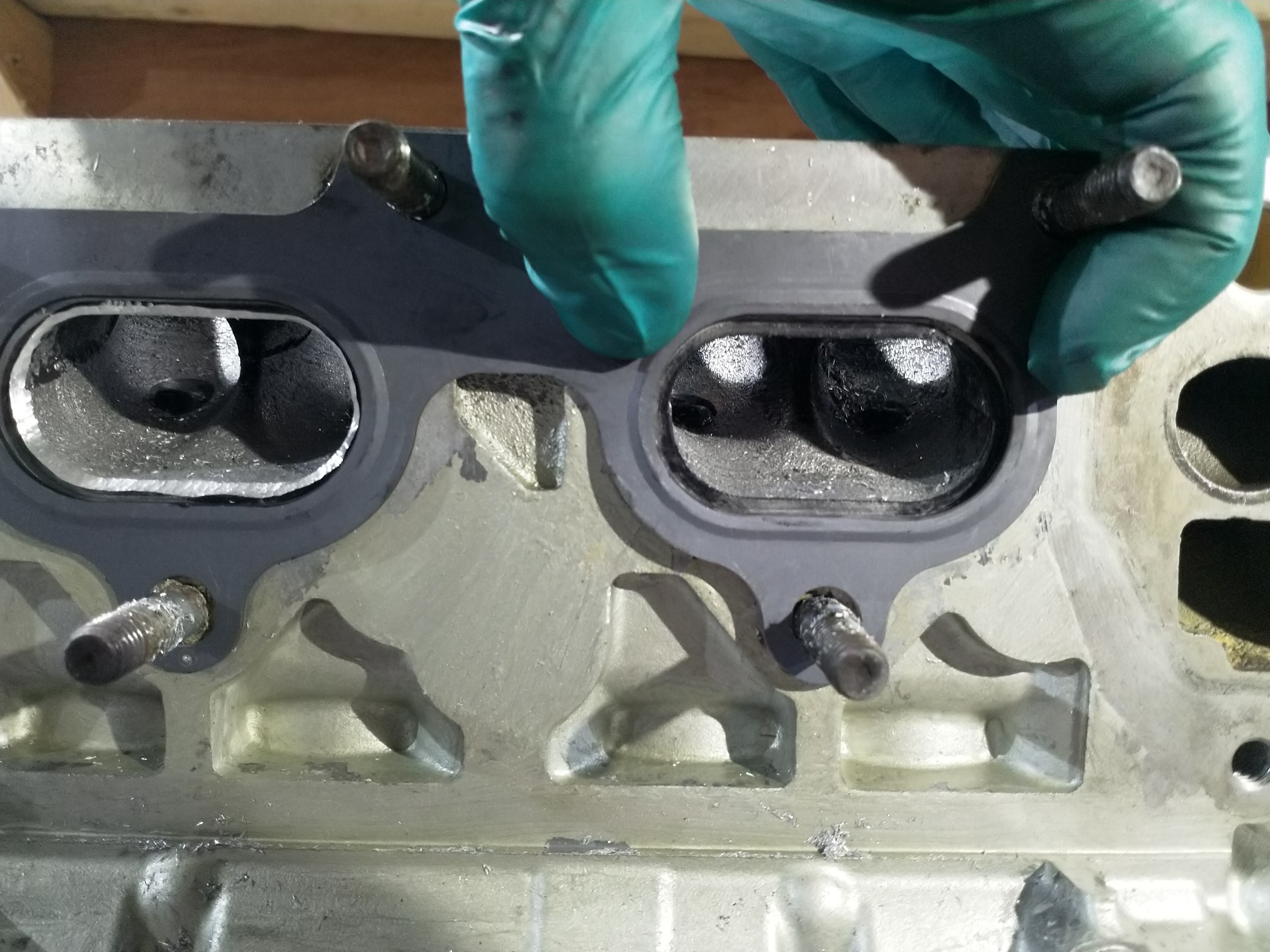
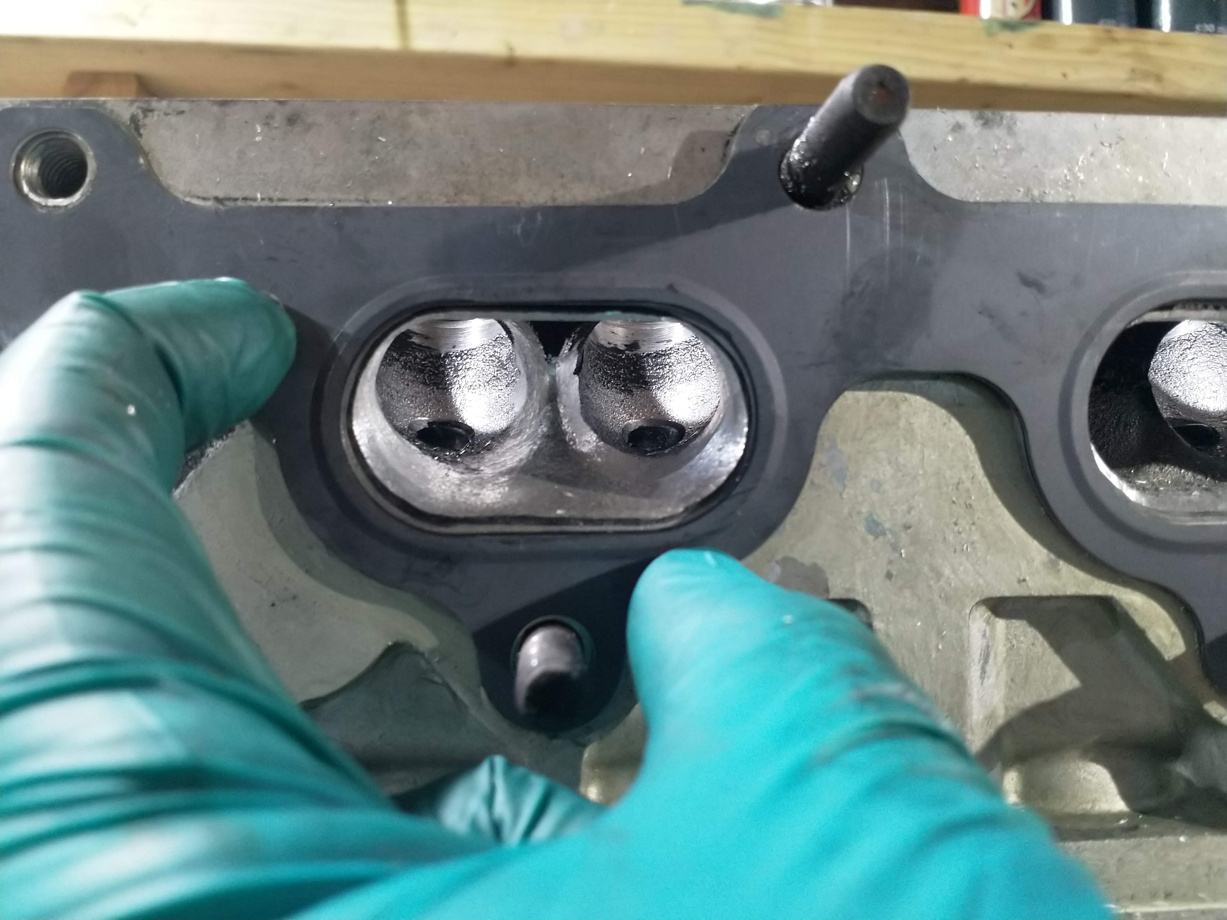
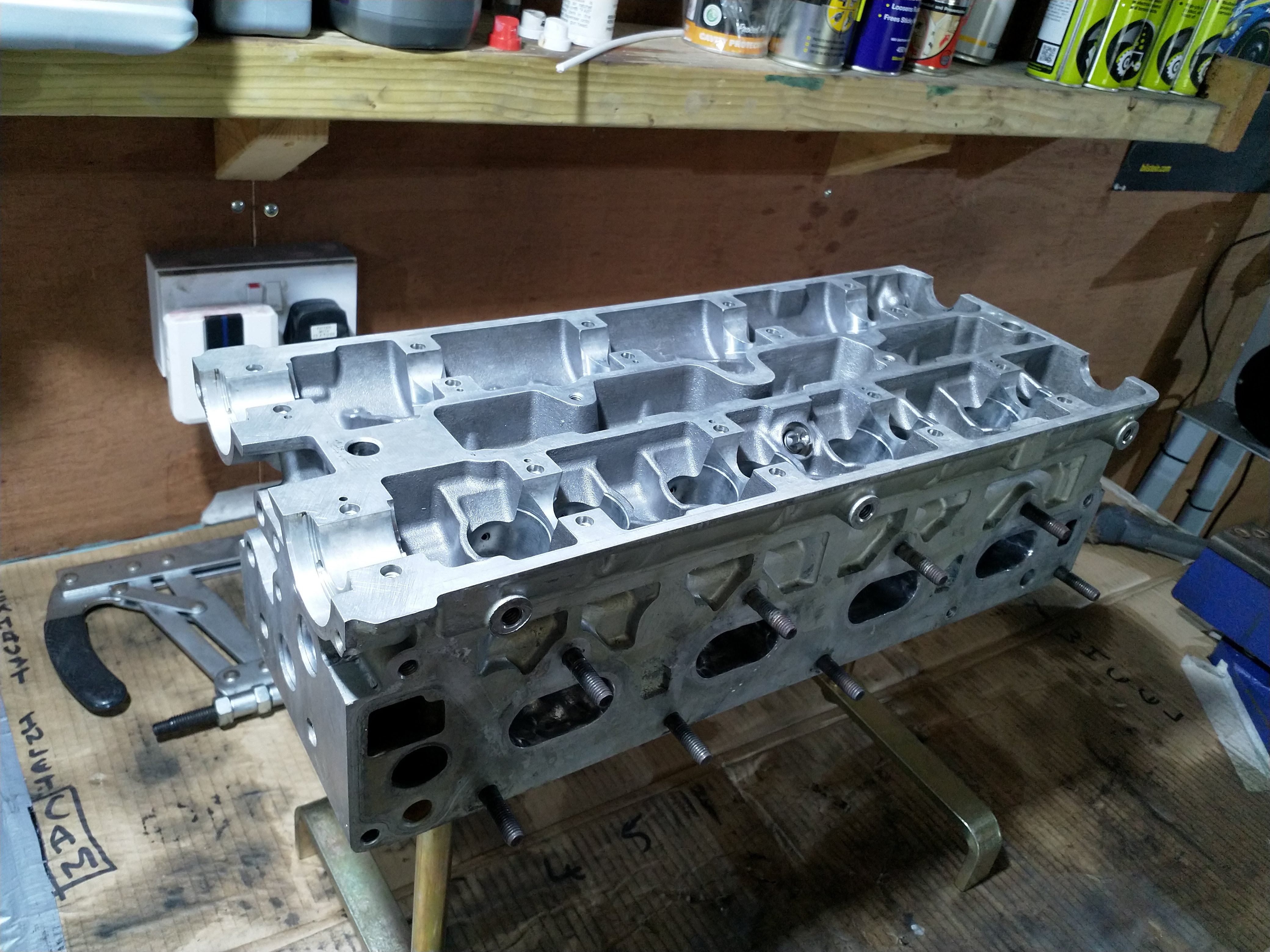
full


Cylinder head on!

full


Had a bit of nightmare with this actually. Not really a biggy but i noticed that the arp instructions for both the conrod bolts and headstuds no longer include ( work the fasterner and up and down 3 times to allow the lube to be spread evenly)
So me being an OCD bugger, I felt i needed to search the internet and see if It existed still

FYI, it doesn't.

But while searching I looked at the headstud instructions on ARP's website for generic kits and it mentioned ' Fit the washers with the chamfer
facing up'

:aaargh: :aaargh: :aaargh: :aaargh: :aaargh:

There was no mention of that in the instruction I got with mine! Luckily i hadn't tightened the head at all due to searching for the other info, so i managed to remove all the washer again, barely barely noticable but it is there. You can fell one side of the washer is sharp and the other isn't.
My poor OCD would of had a melt down if i had found that further down the line!

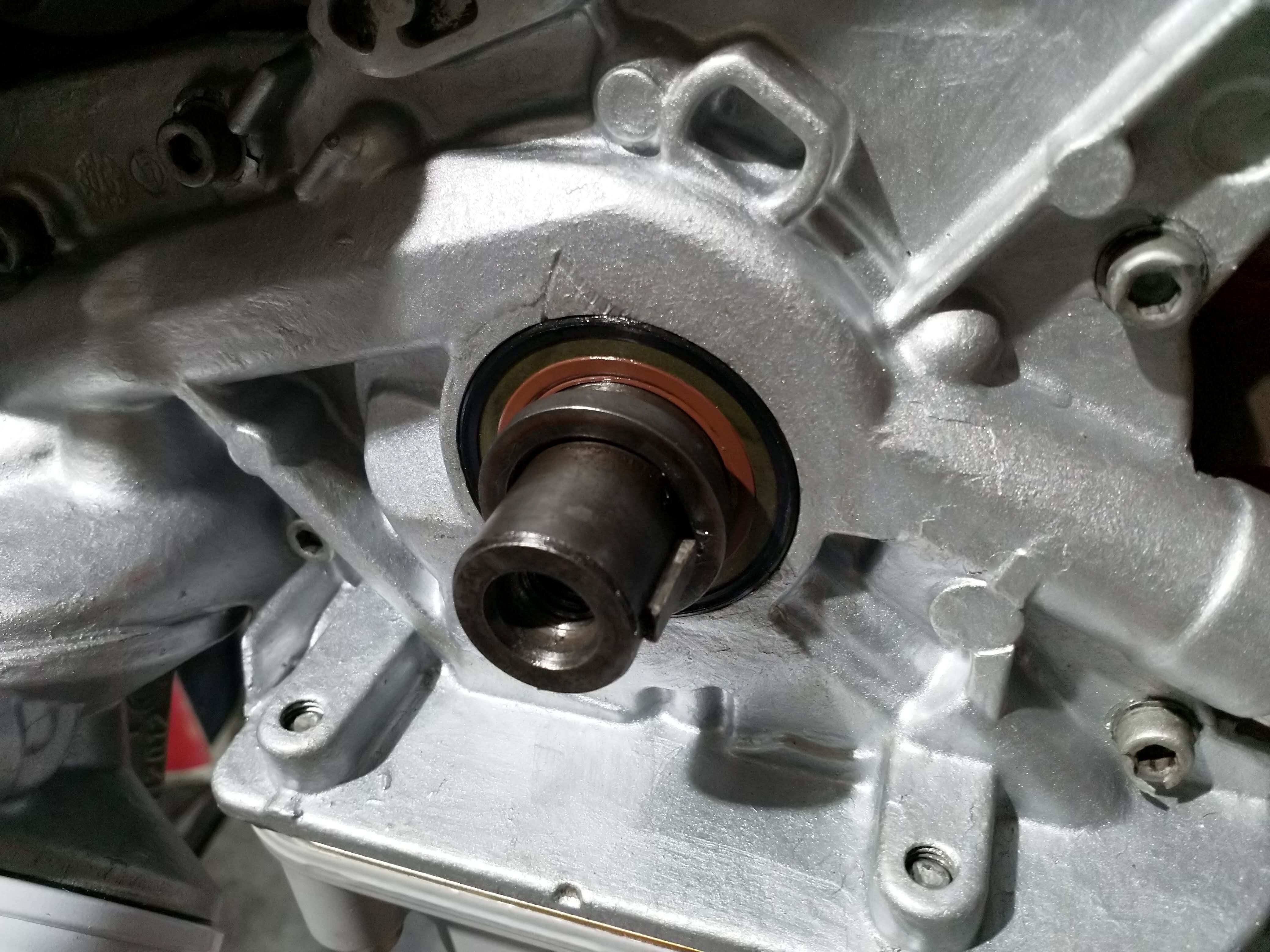
All good though, next crank seal in (easier to do this with the pump on as you can use a 36mm socket and long bolt in the crank and press the seal in flush with a bit of grease to help)

full


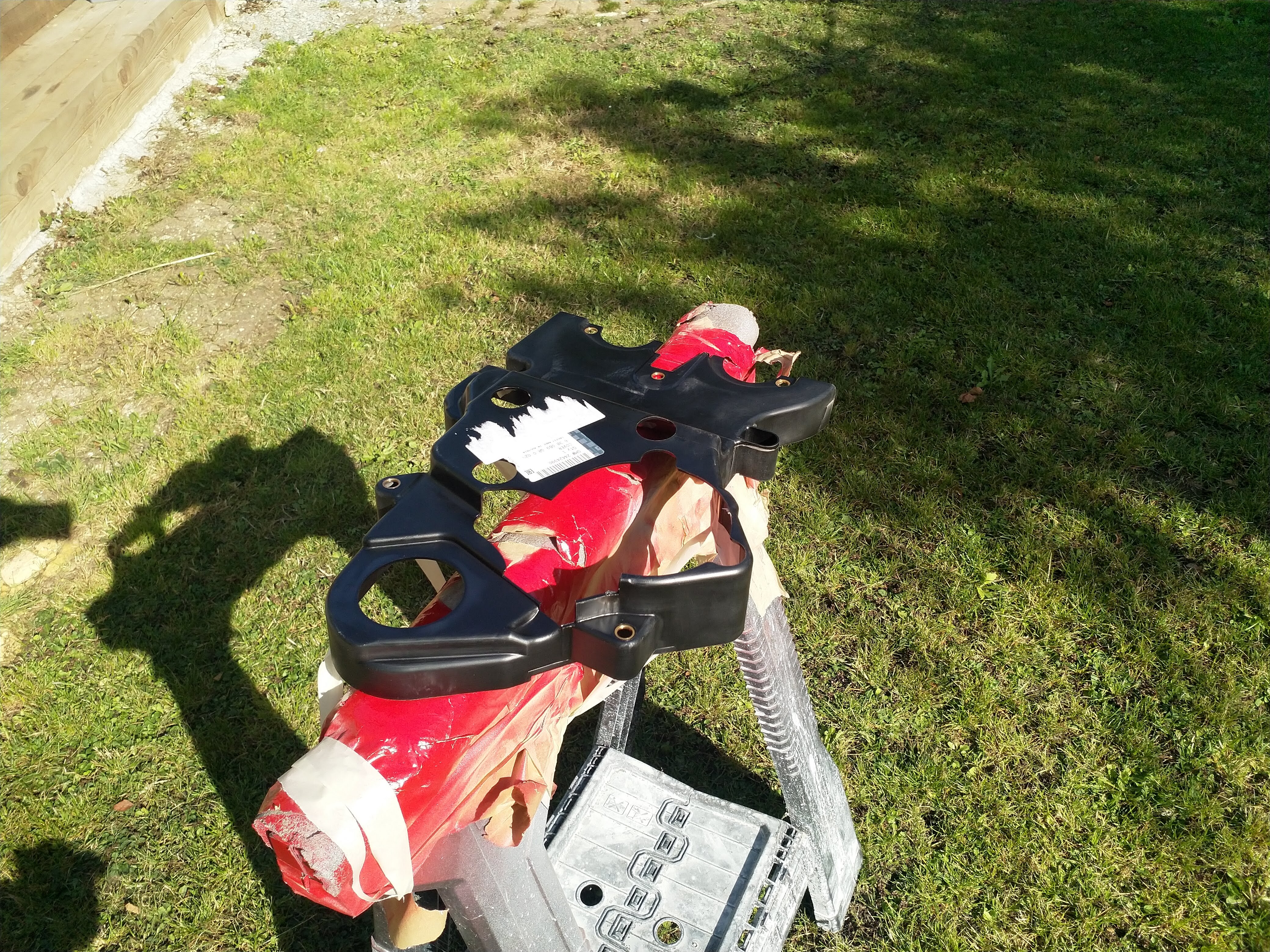
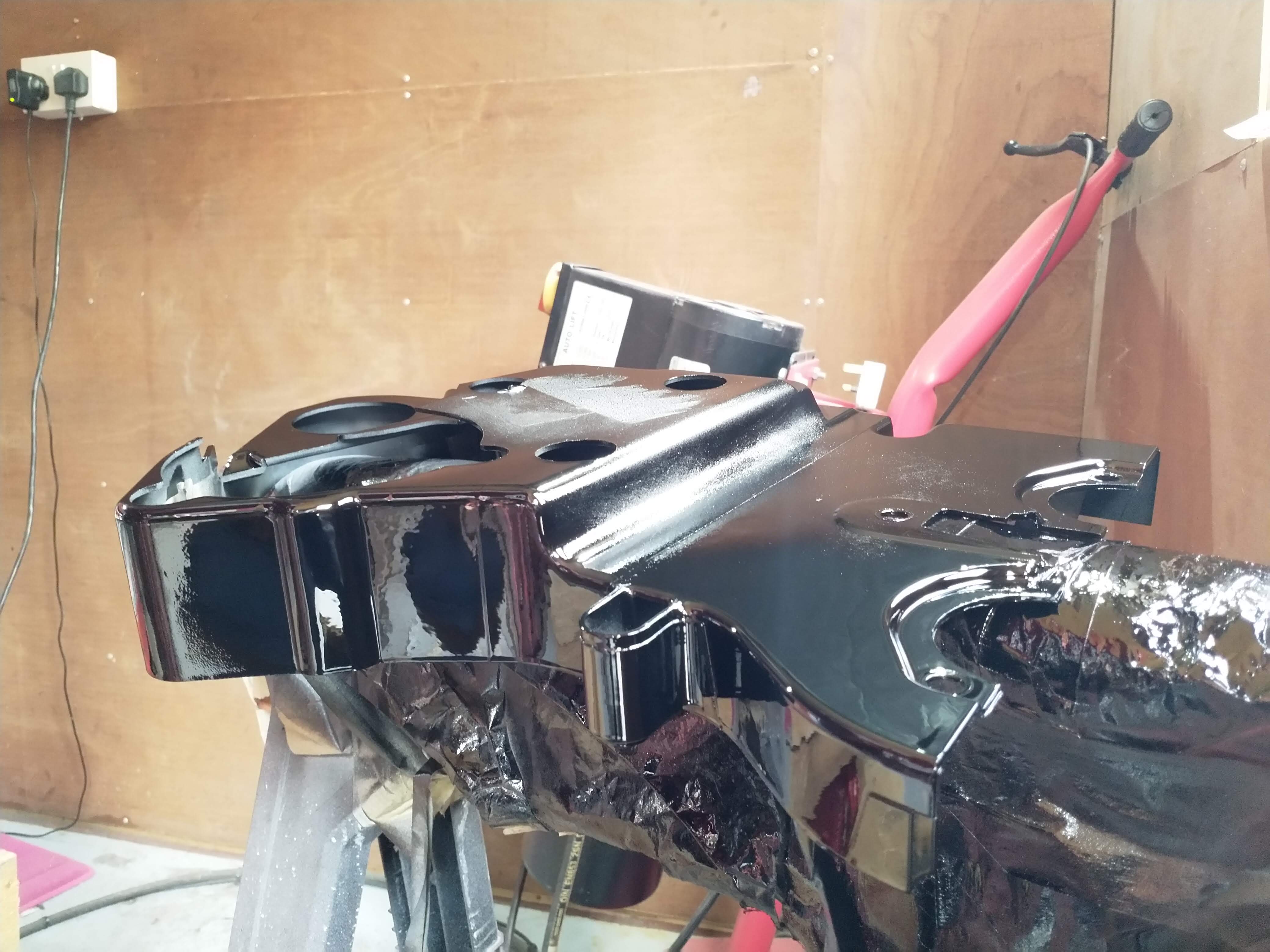
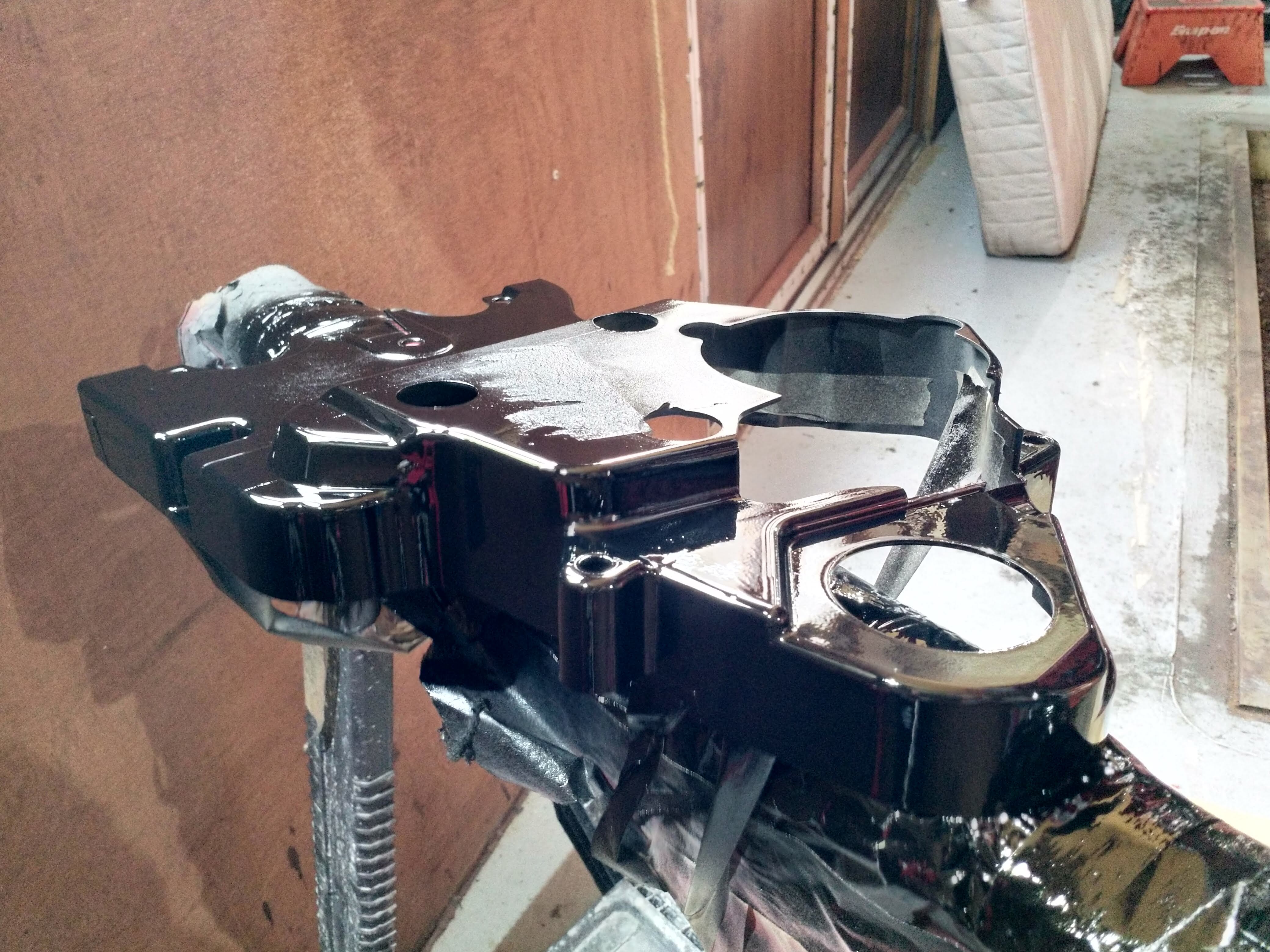
Rear timing cover outside for painting, I did this in 2k from a gun on my drive :lol:

full


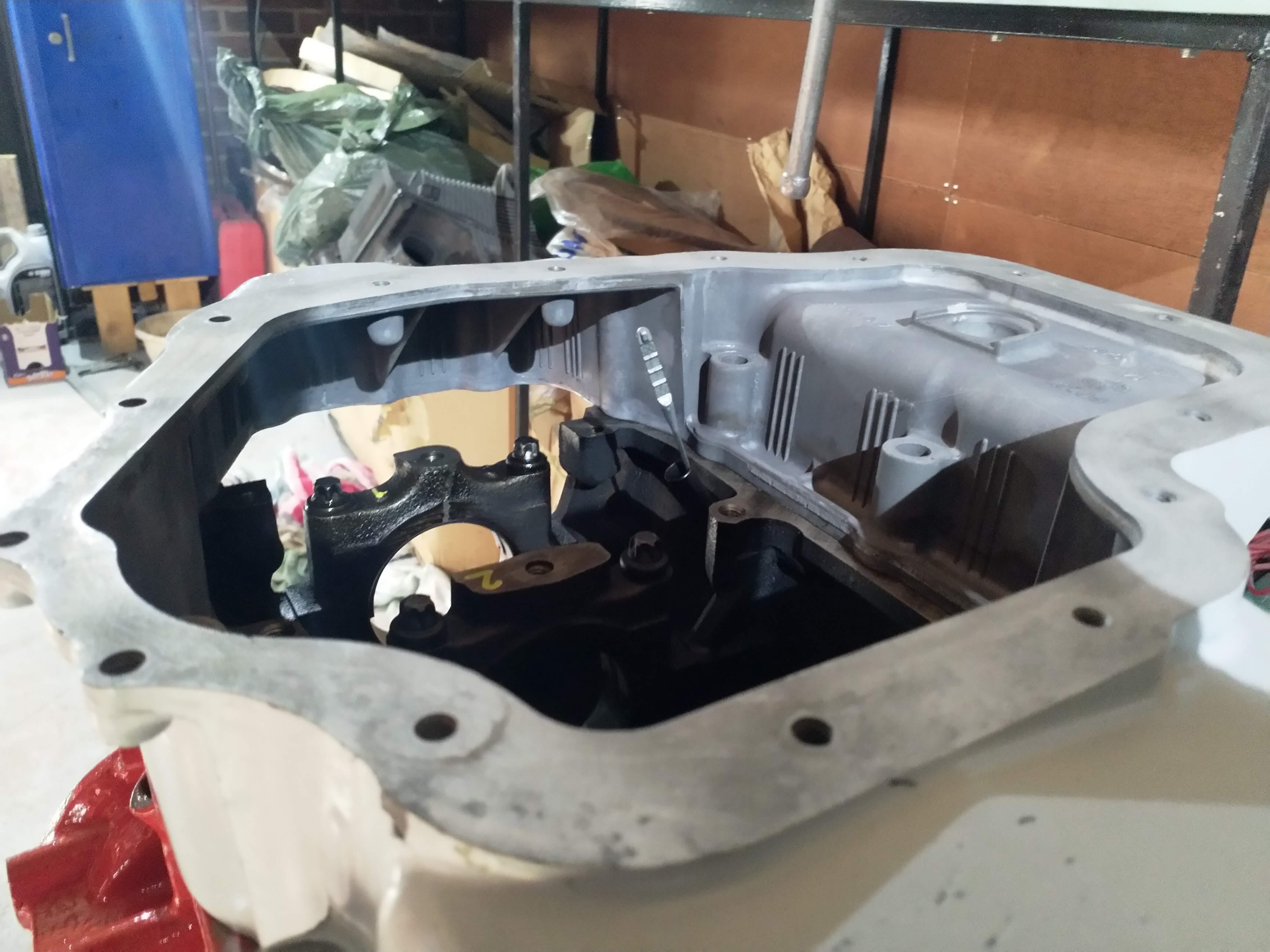
in between coats, sump on, all the powder coat goodness is appearing now. I was sure to clean all mating surfaces of powder coat and clean everything incase of sand etc
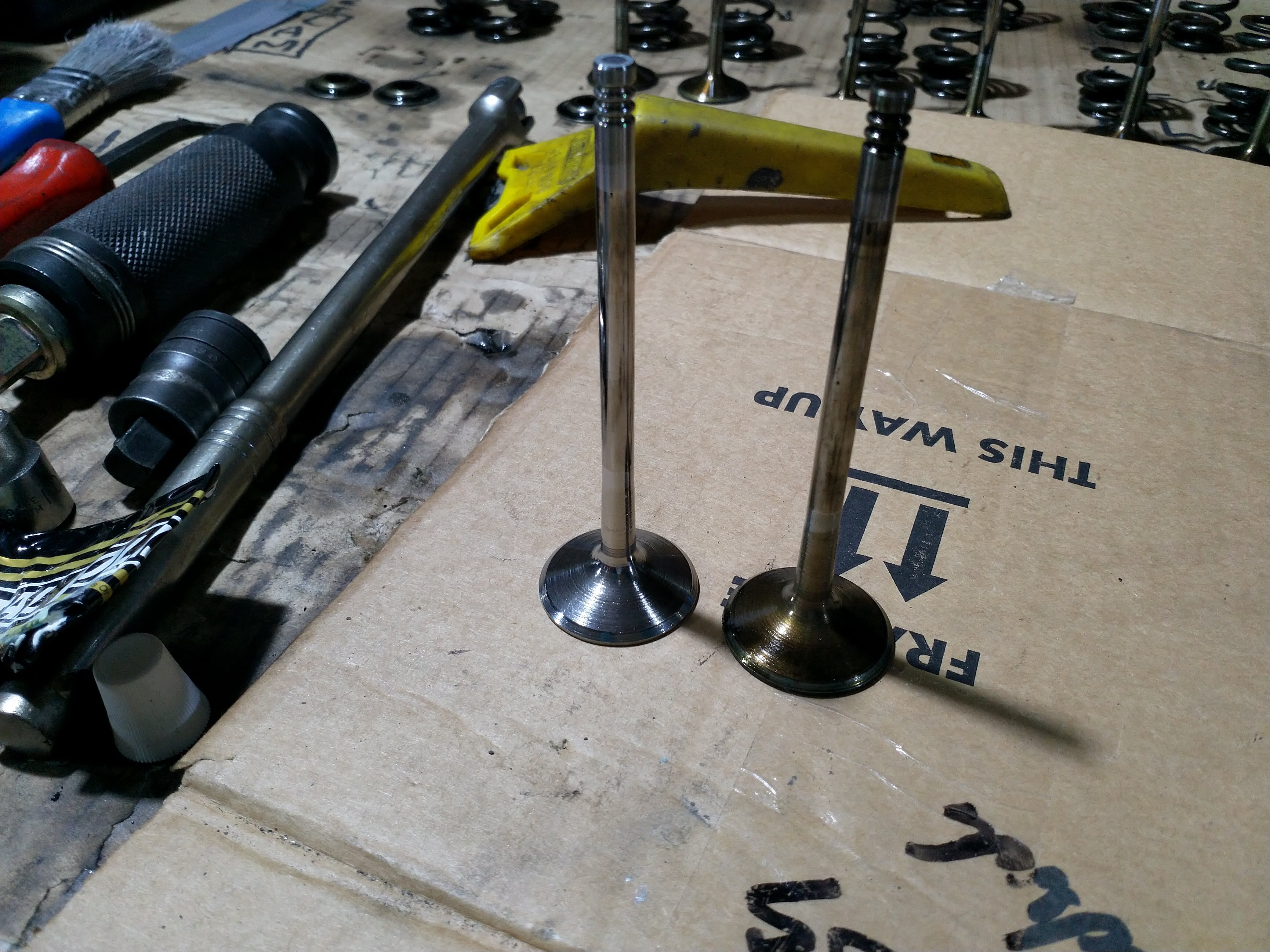
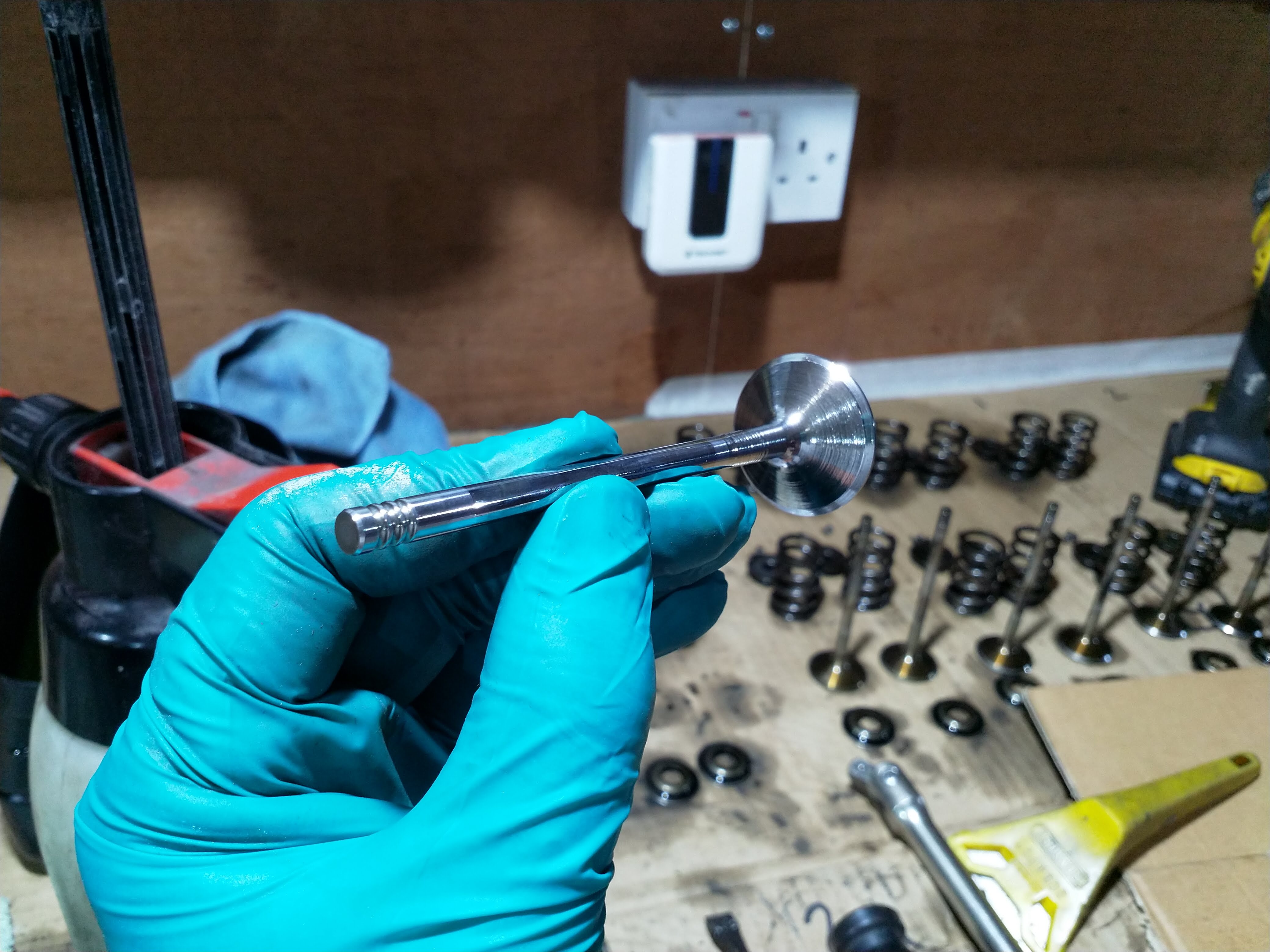
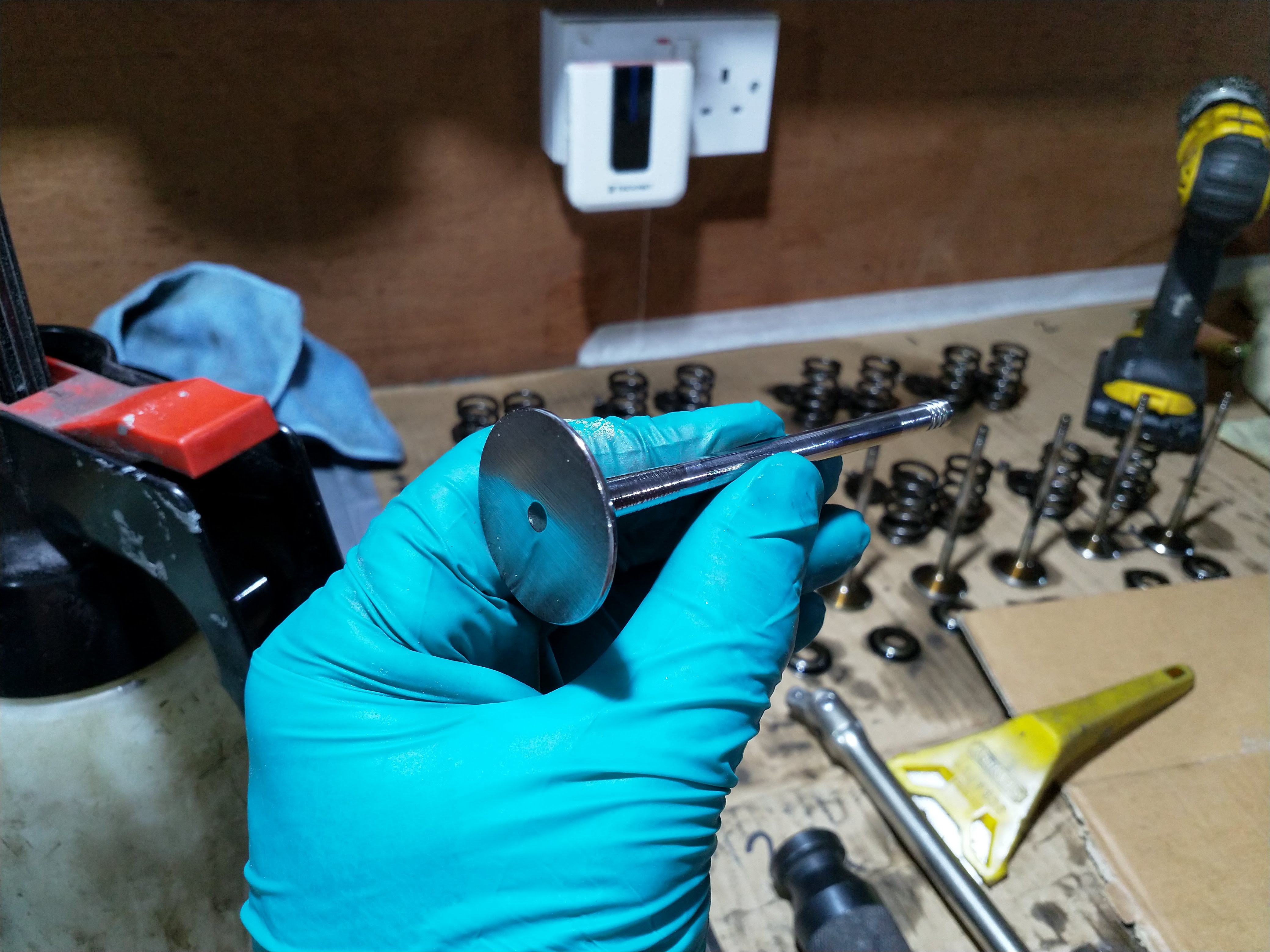
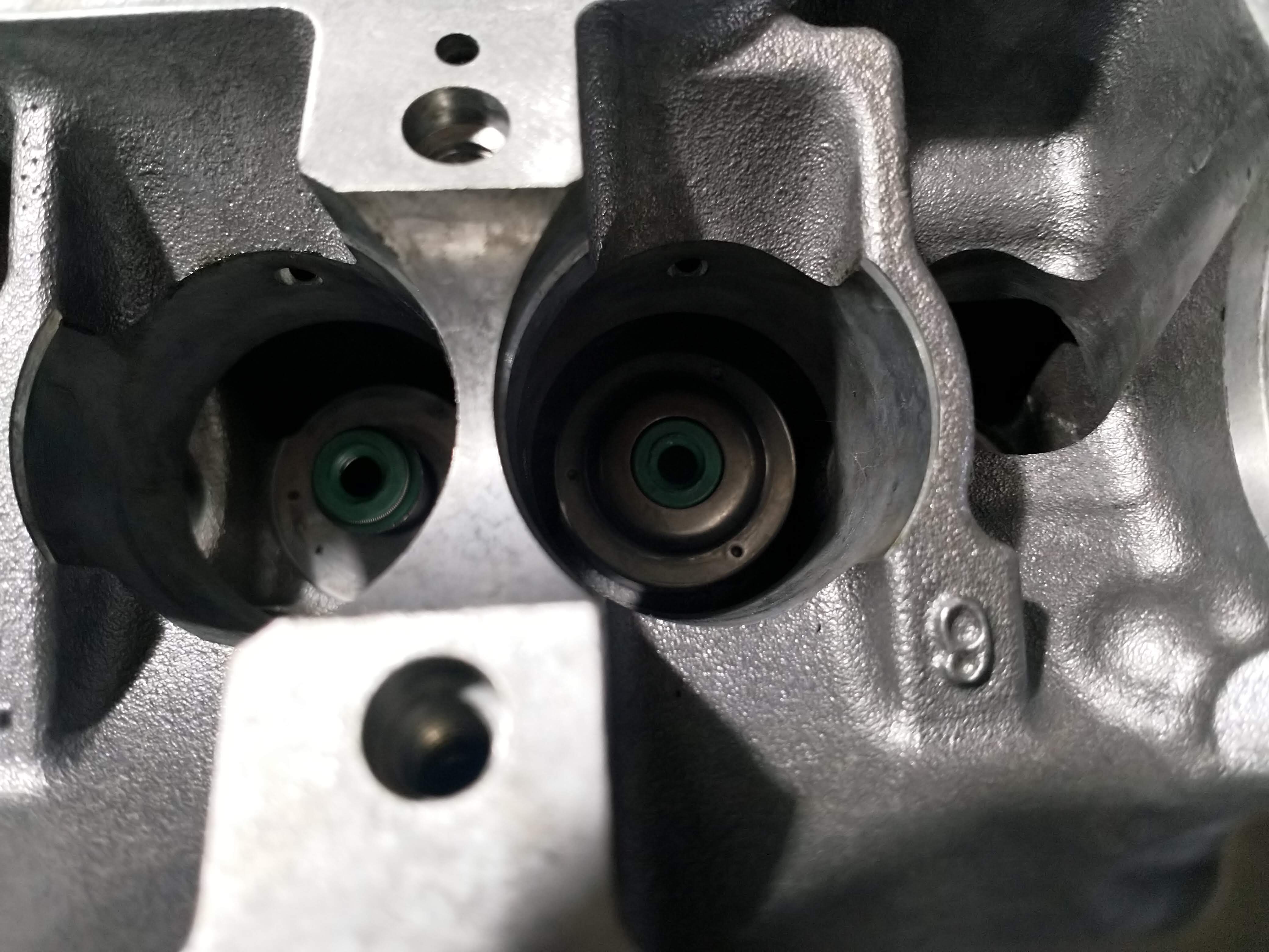
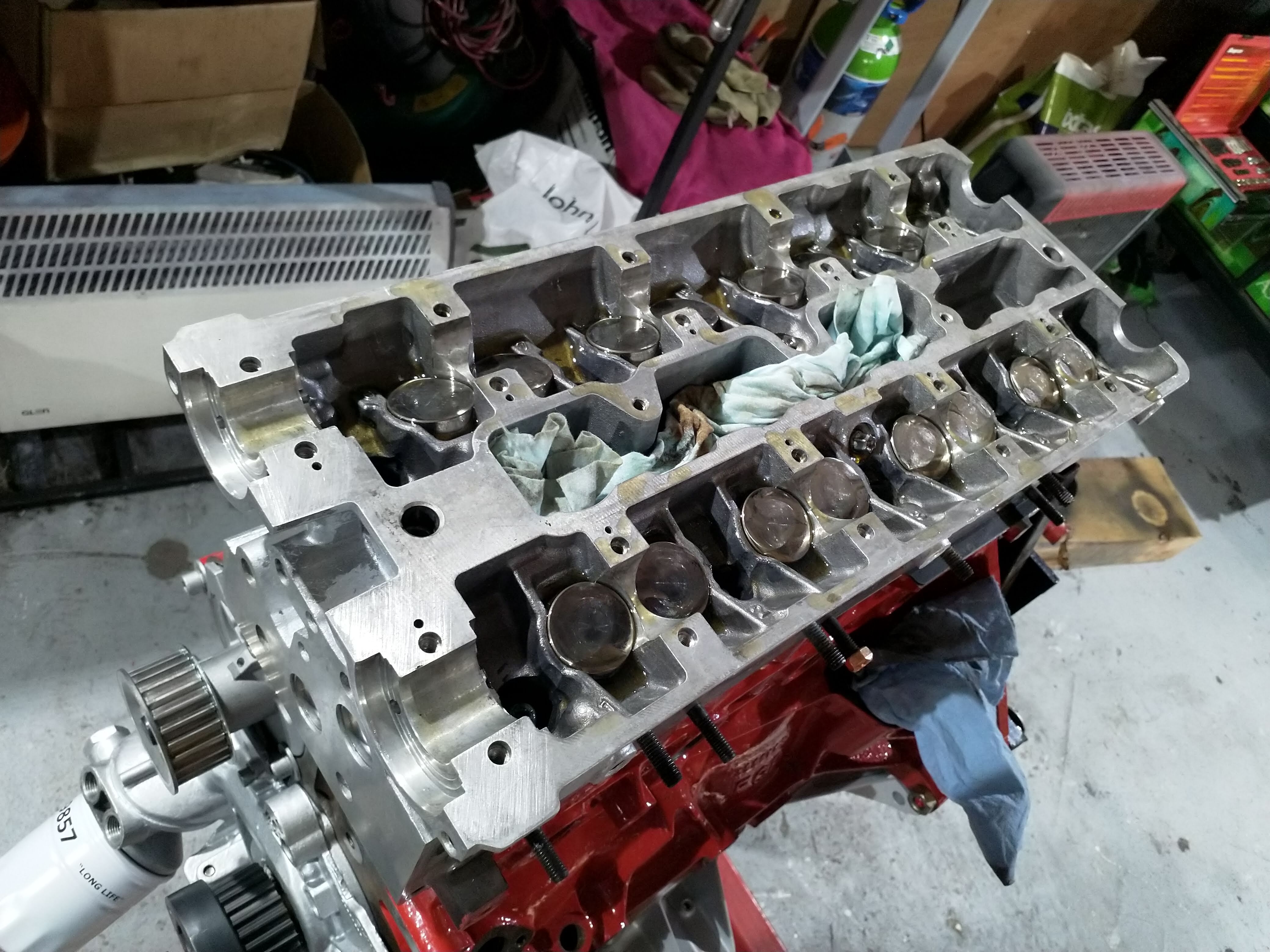
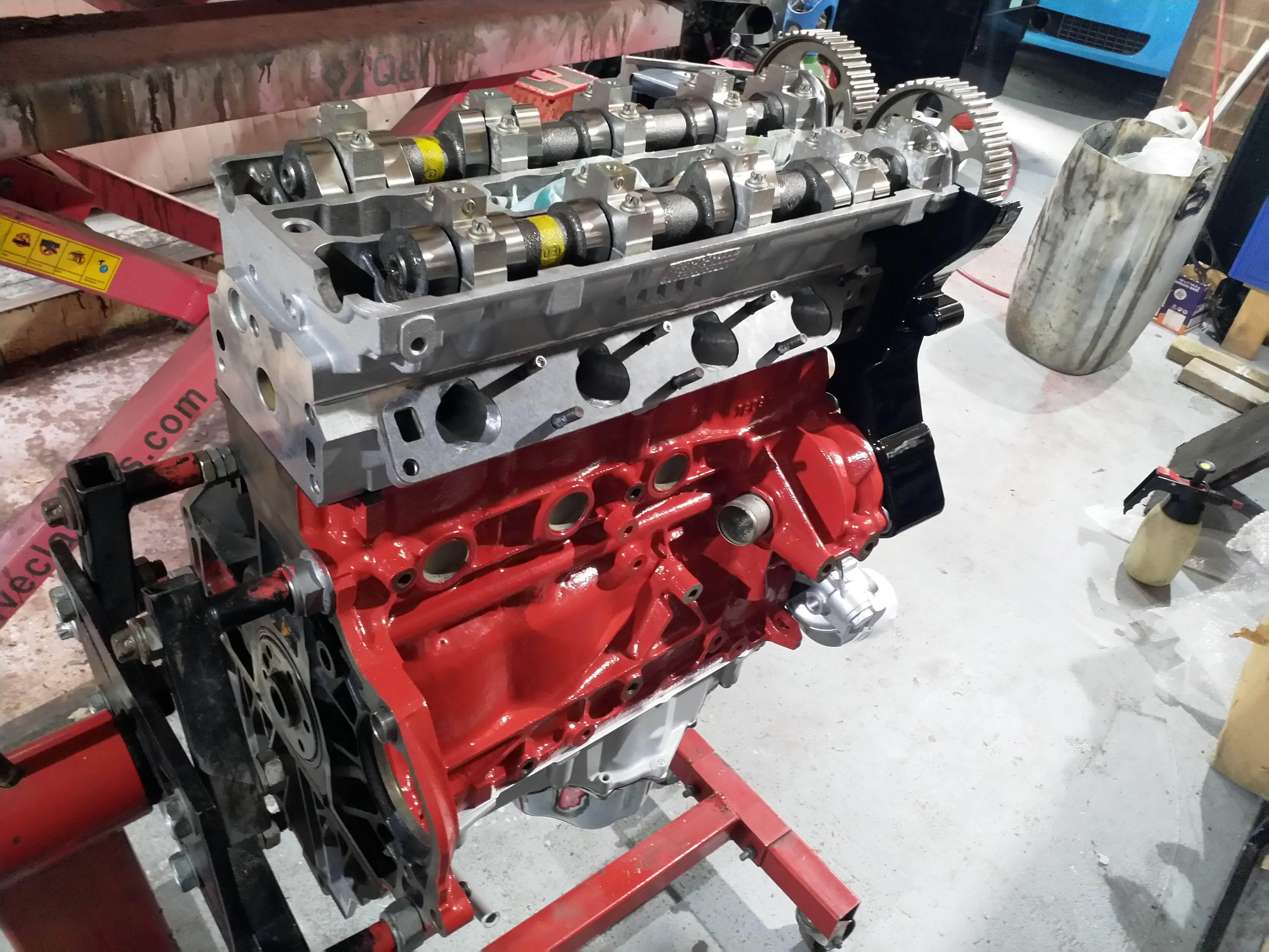
full


tappets in

full


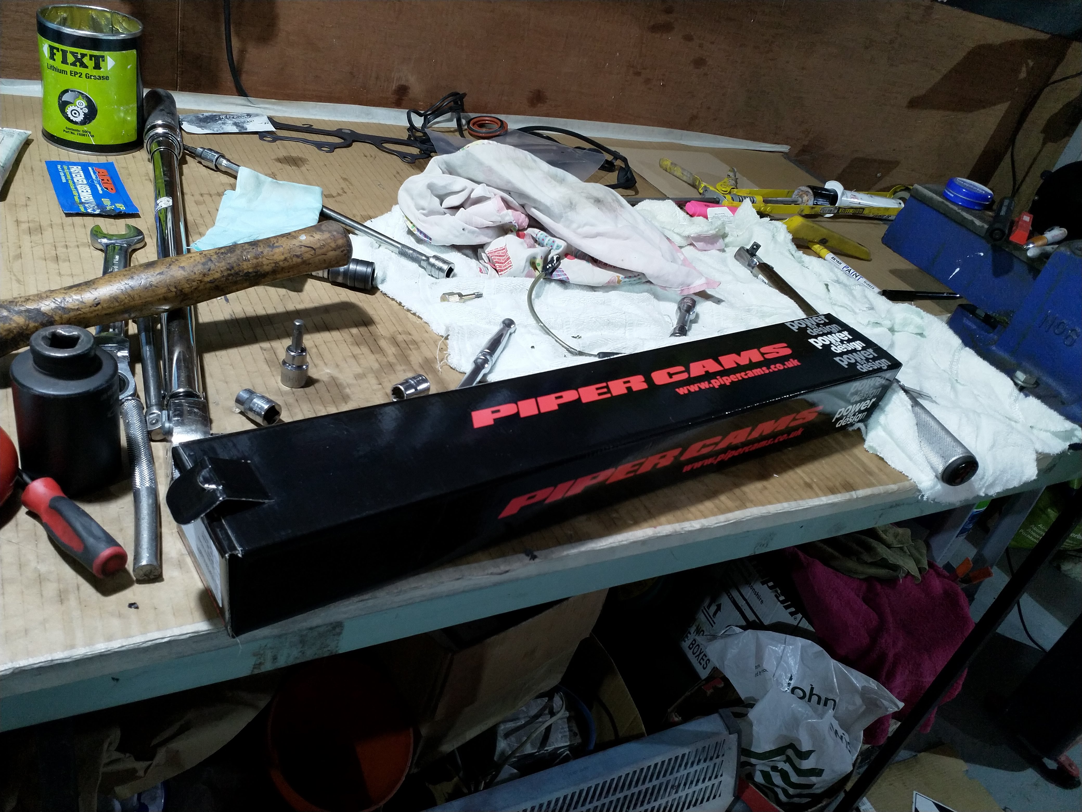
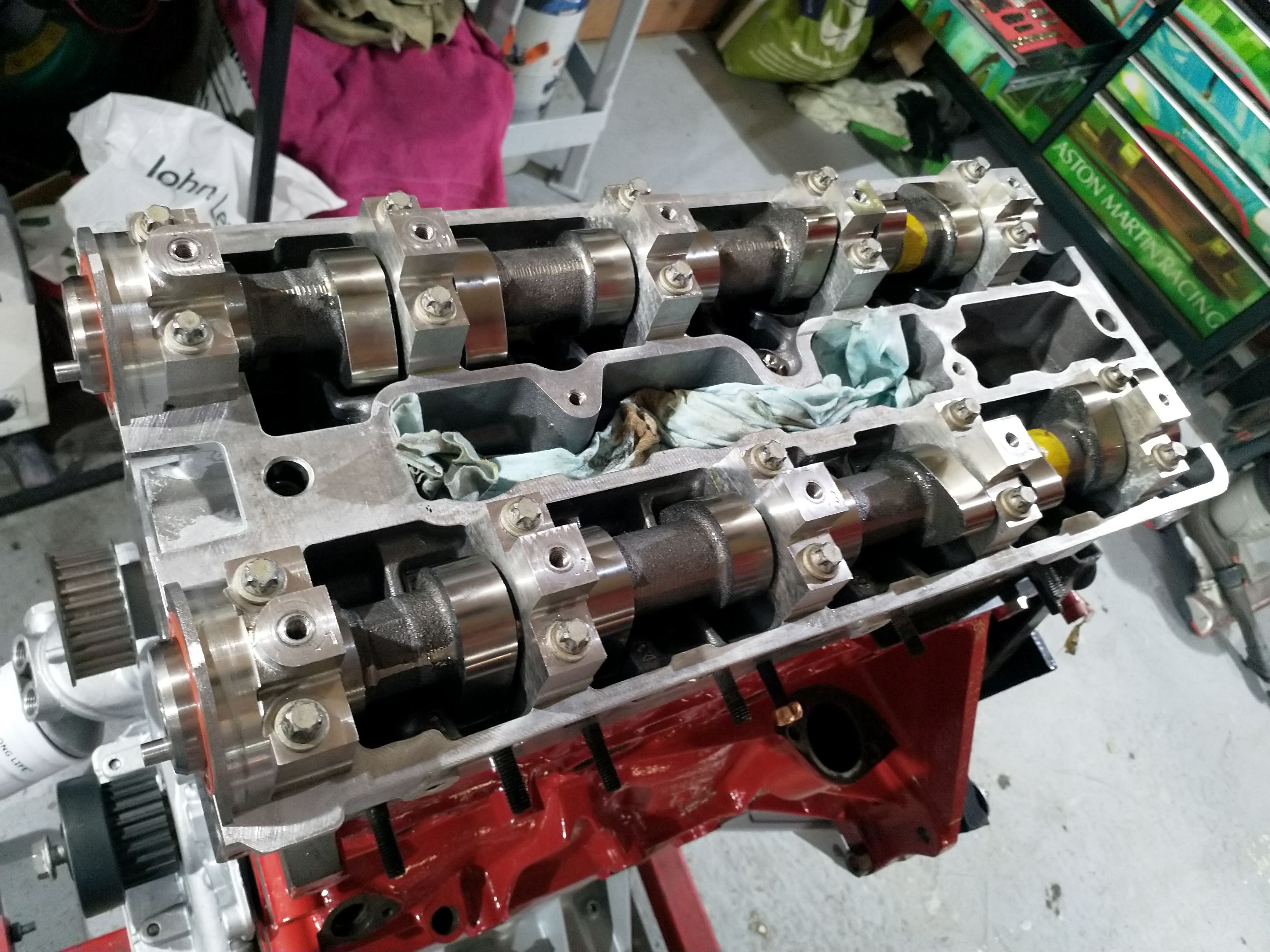
Piper ultimate road cams going in

full


full


timing cover all done, came out brilliantly haha

full

full


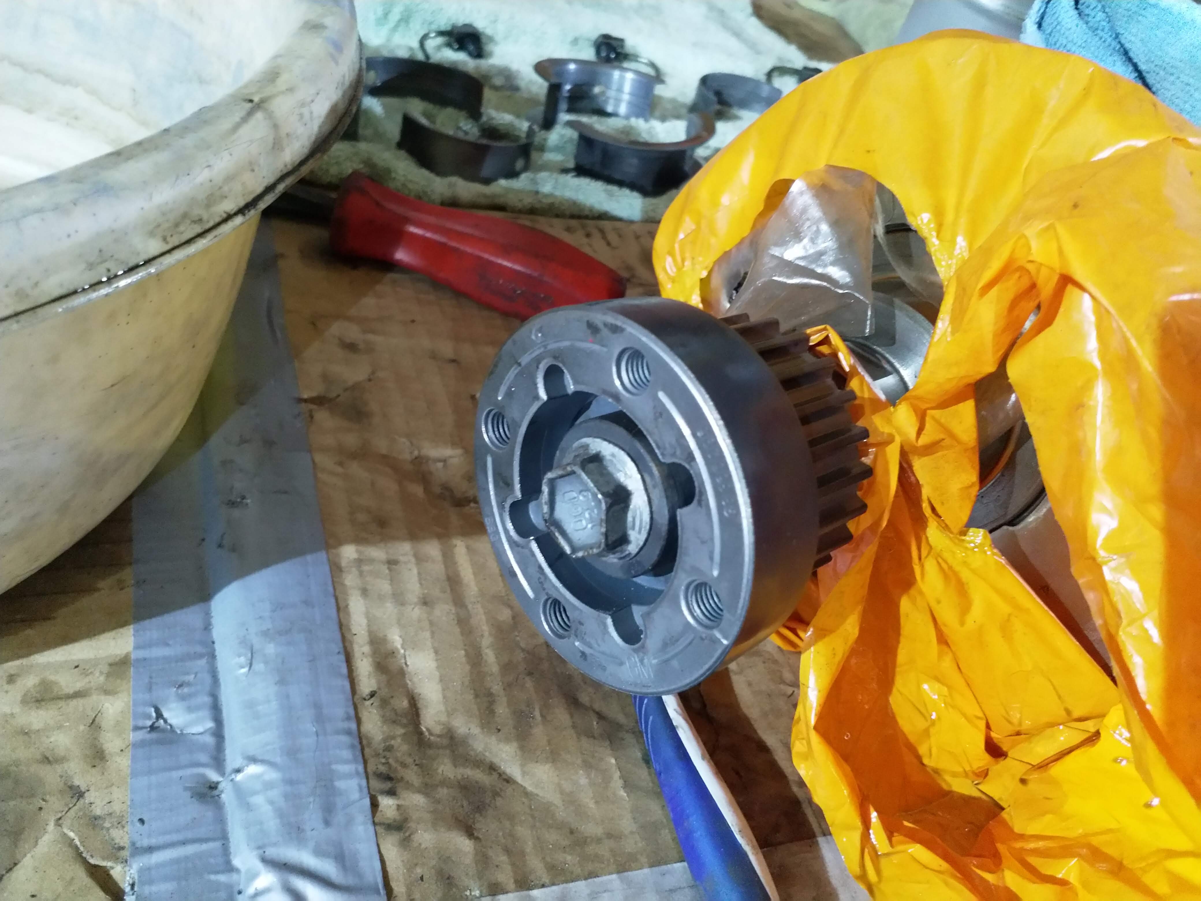
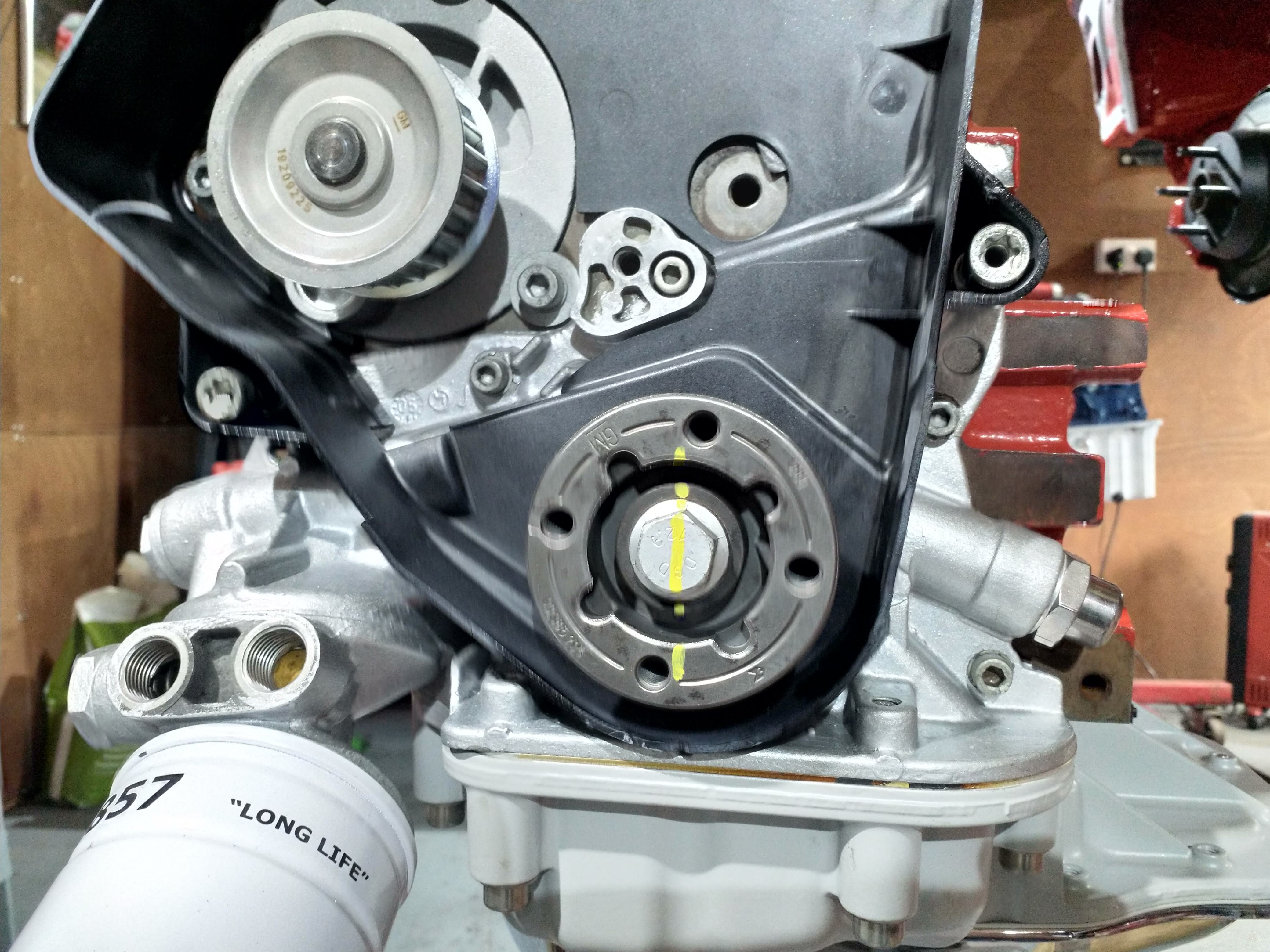
Cover on (careful to hook it behind the water pump incase the waster pump need to be changed!) Crank pulley on, new bolt, torqued up

full


full


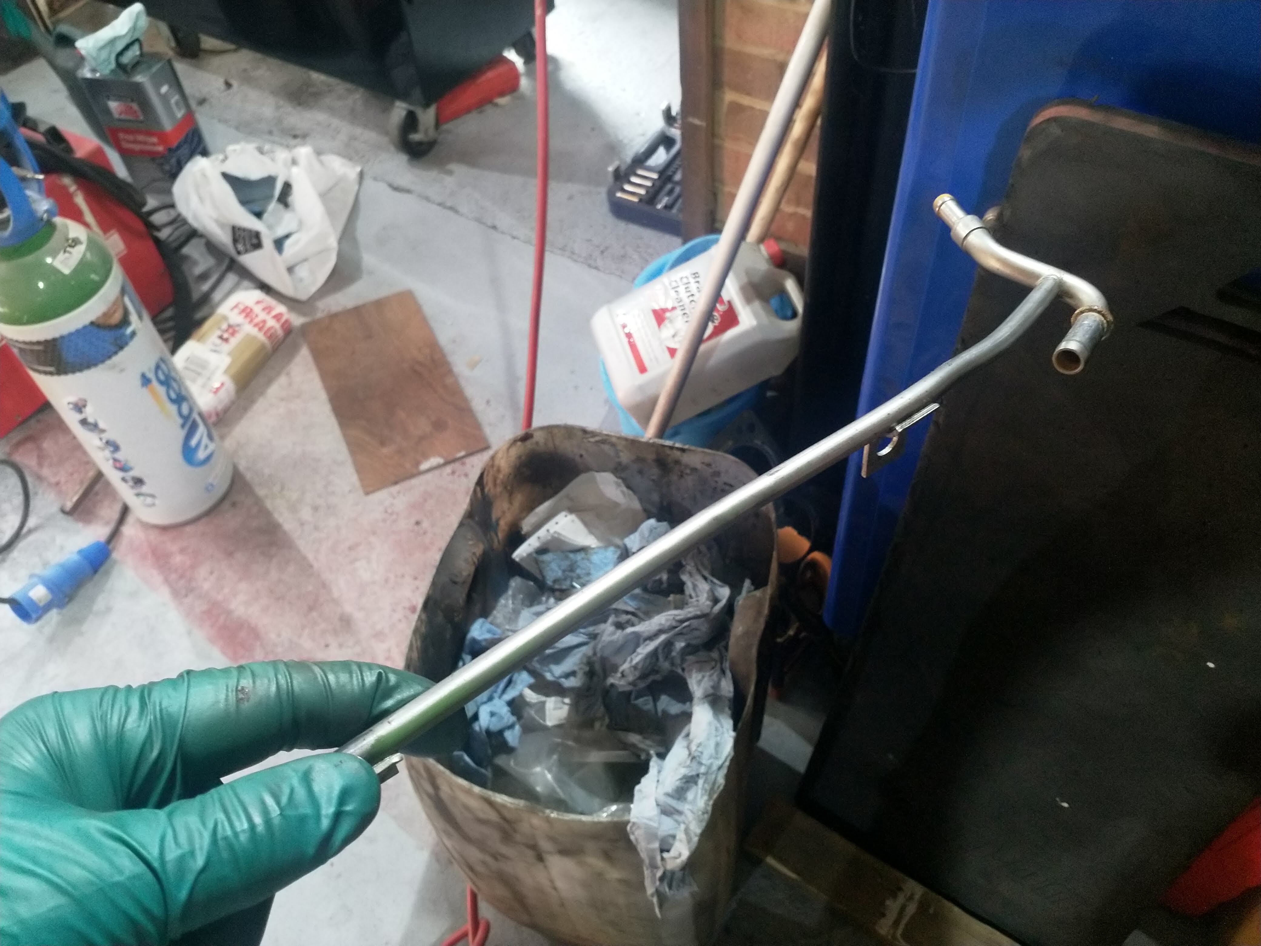
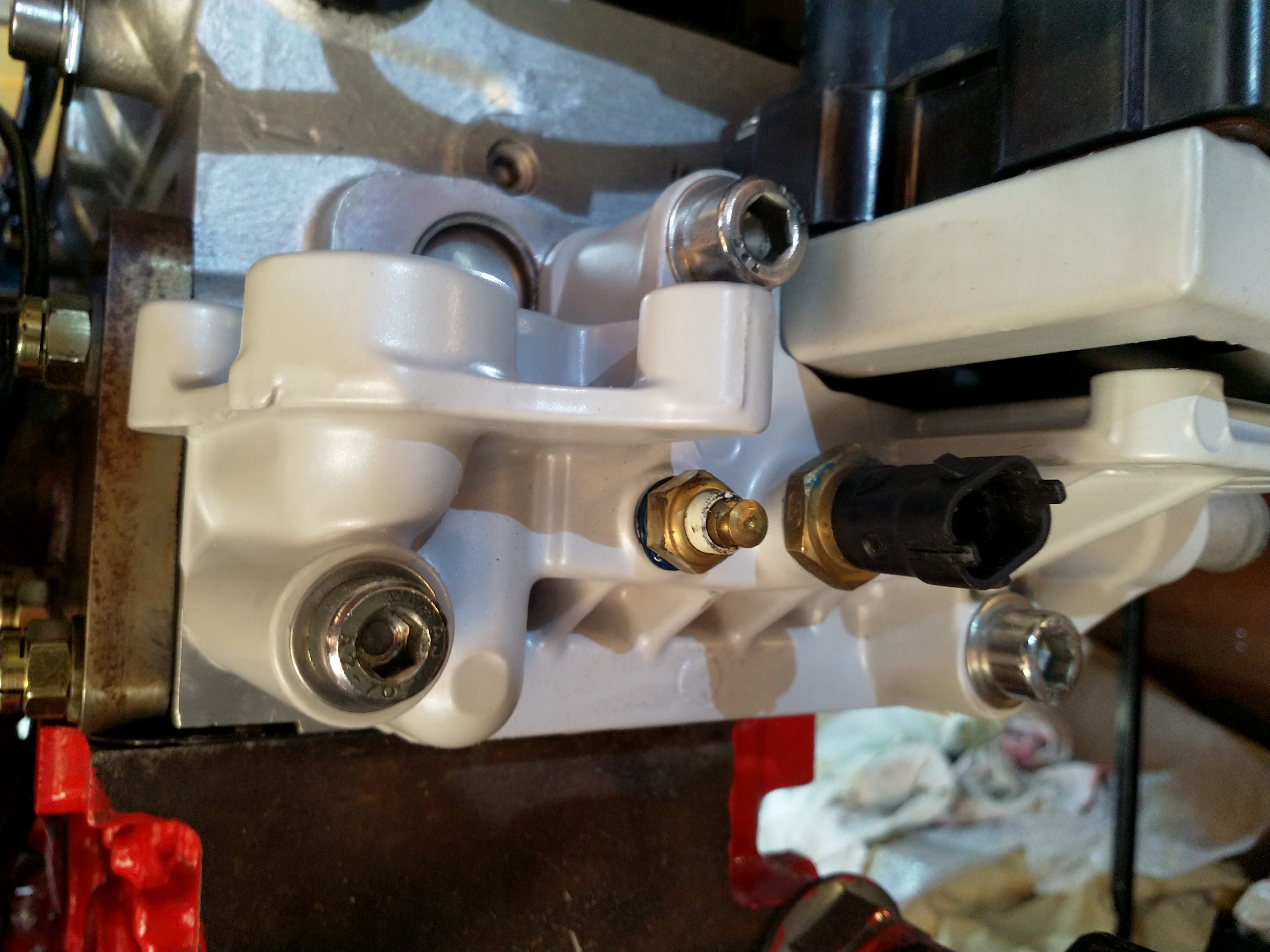
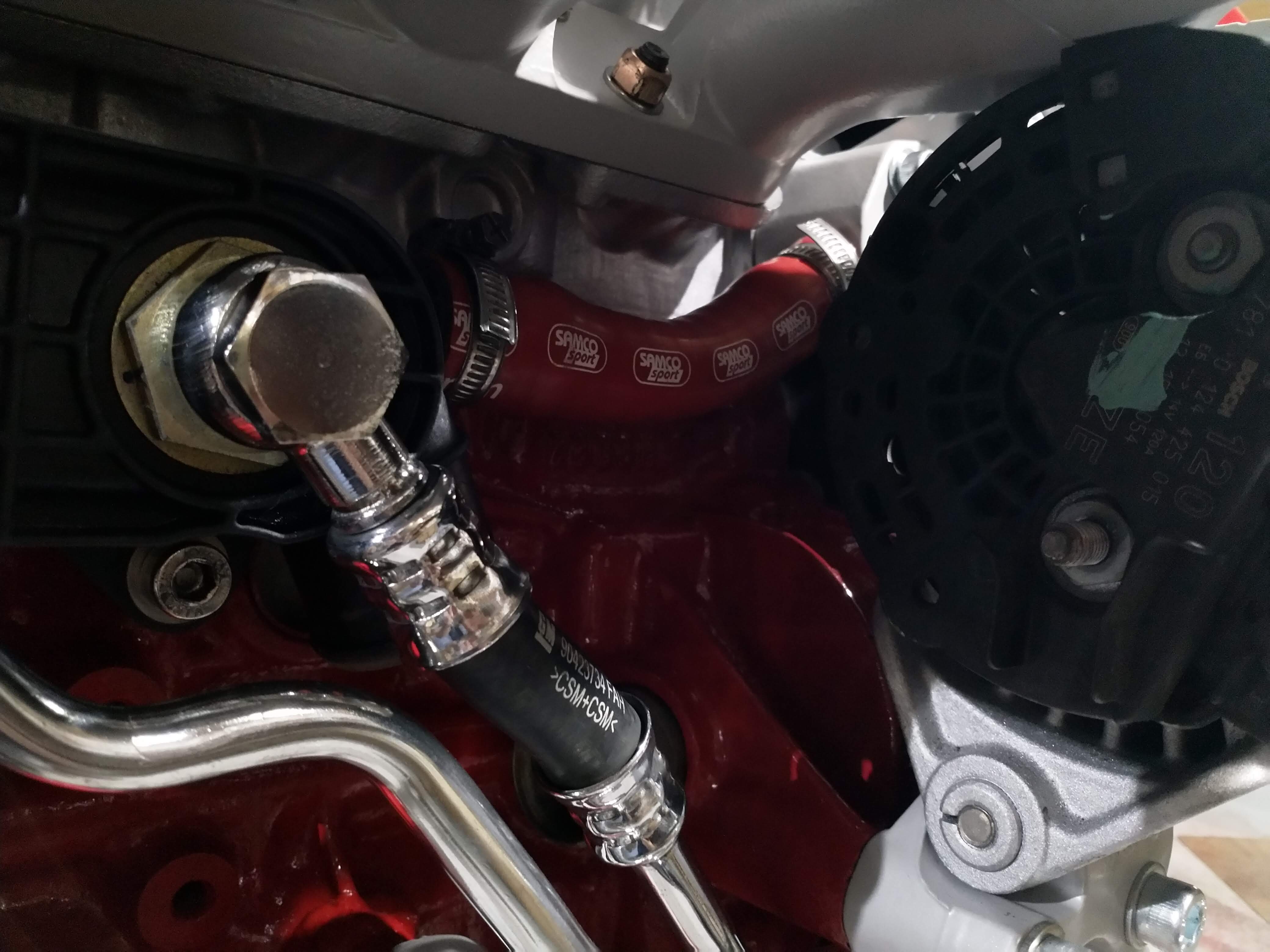
water outlet housing

full


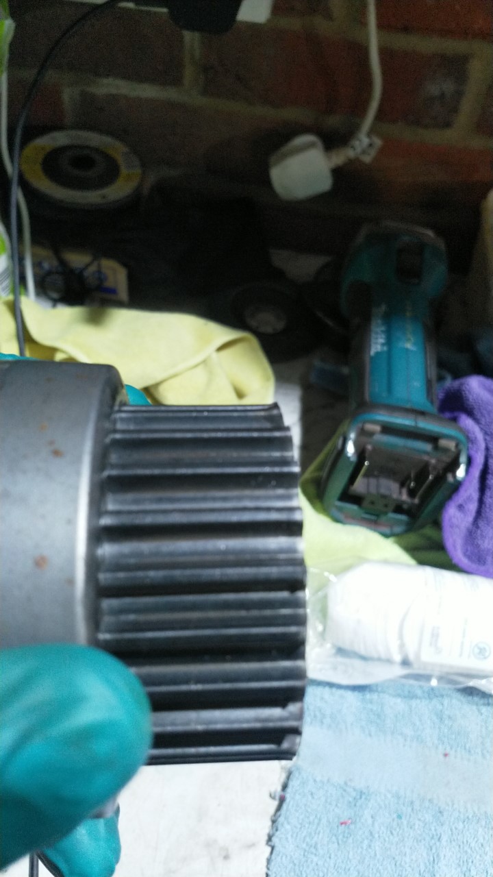
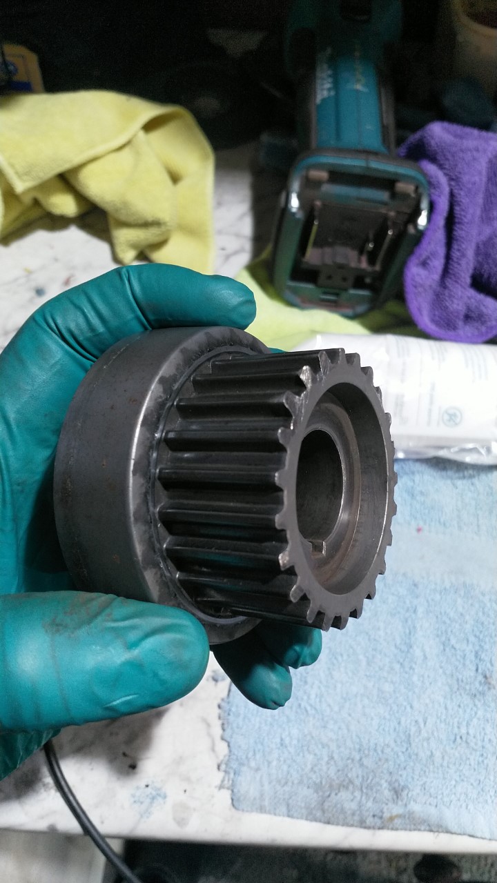
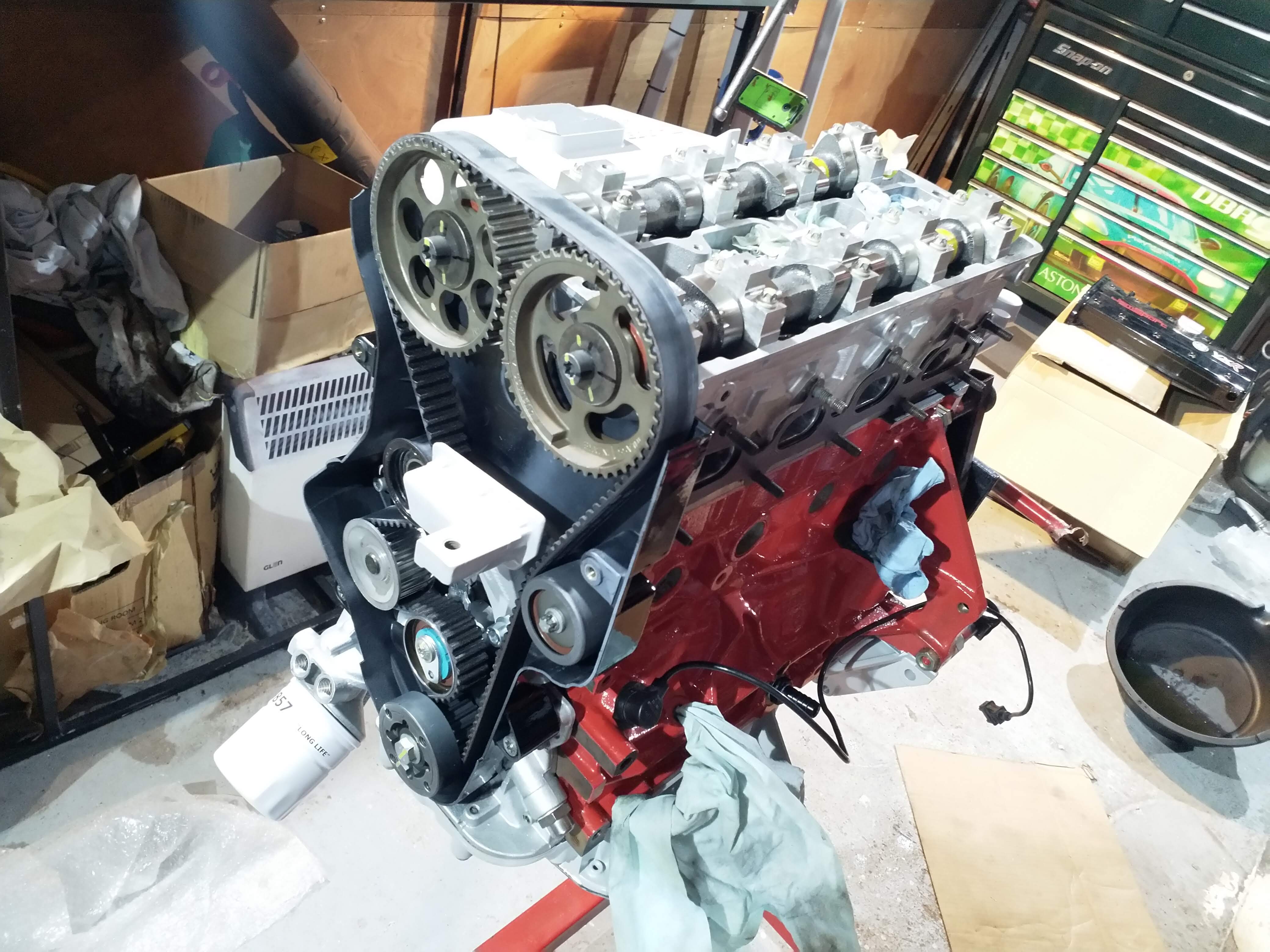
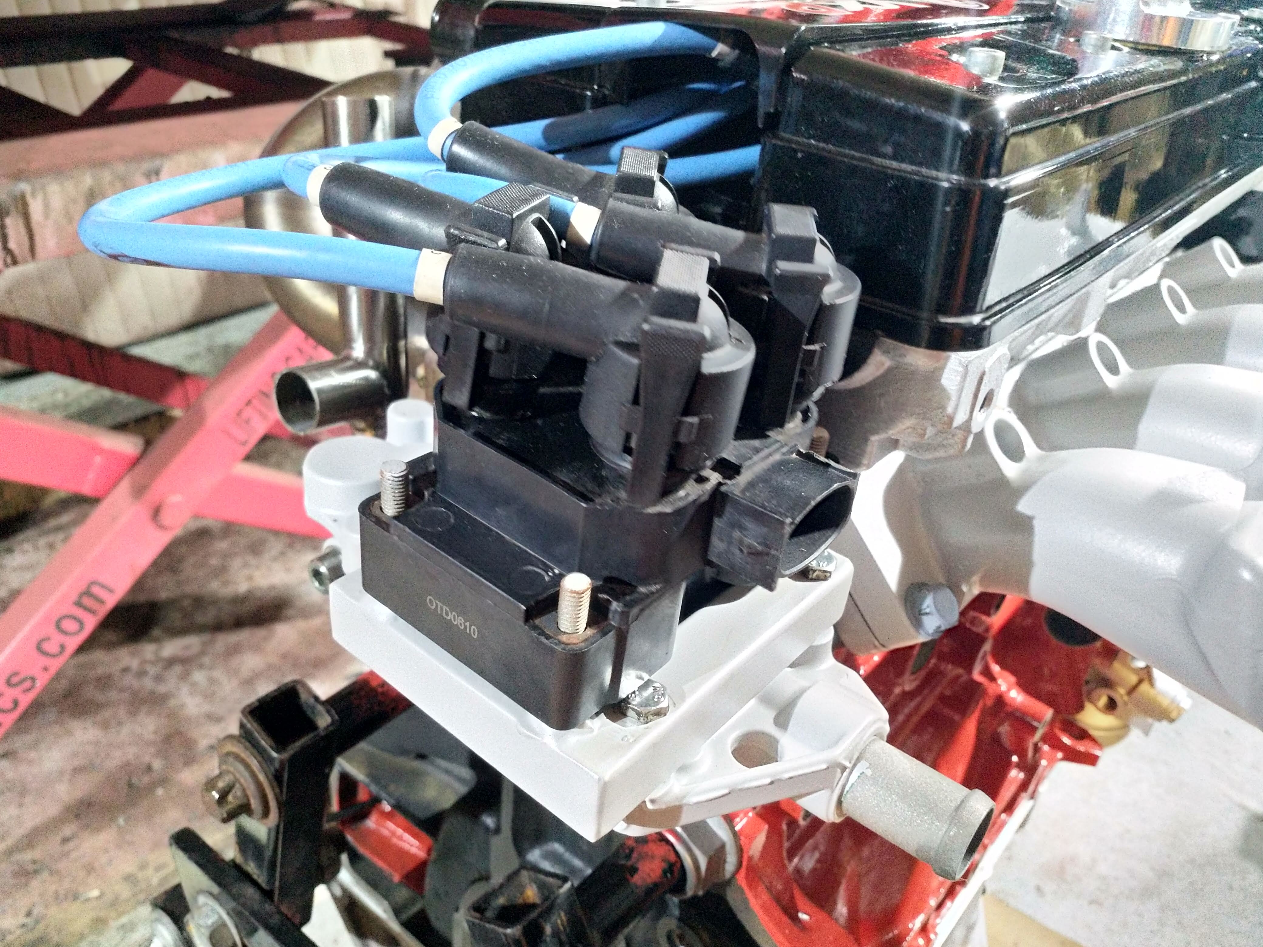
Timing belt and cam pulleys on!

full


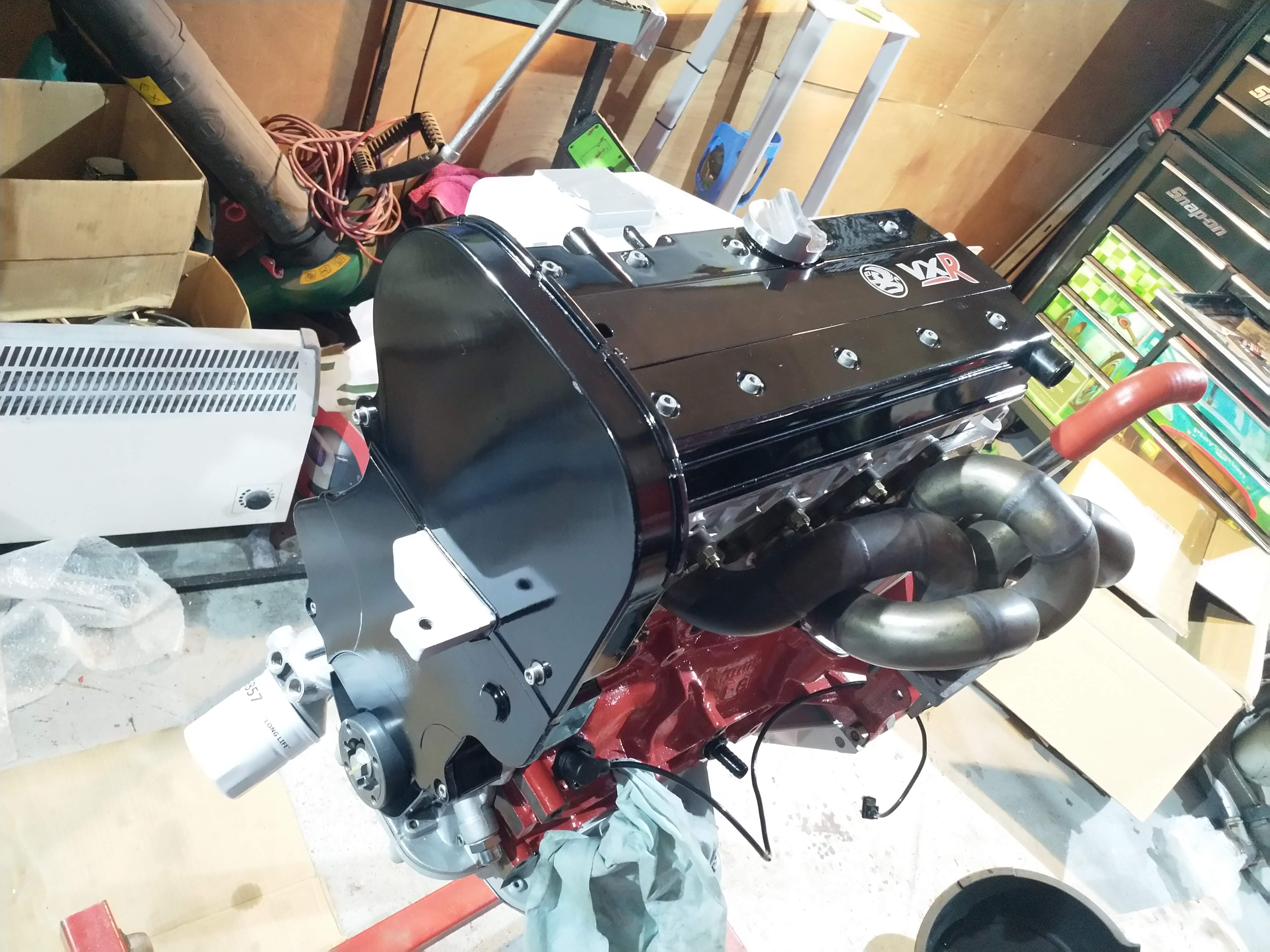
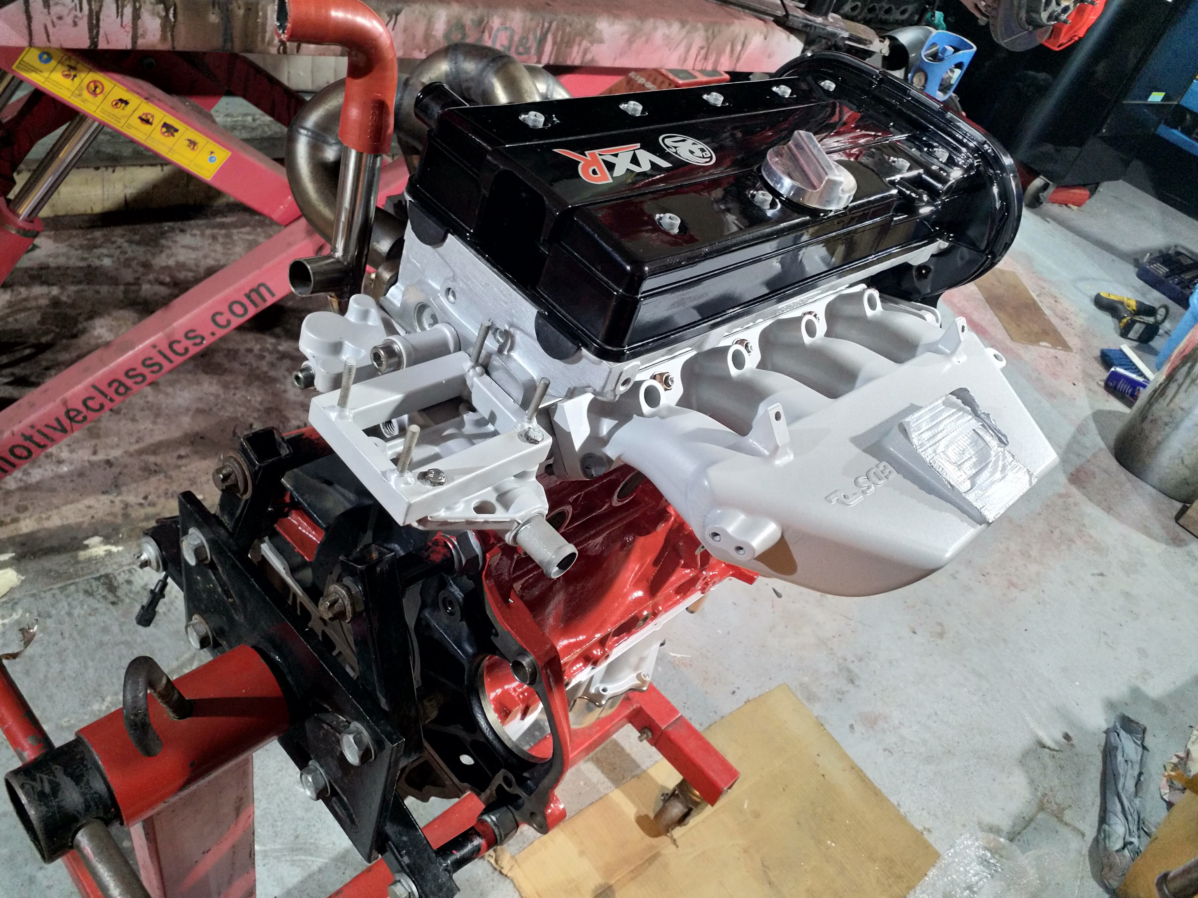
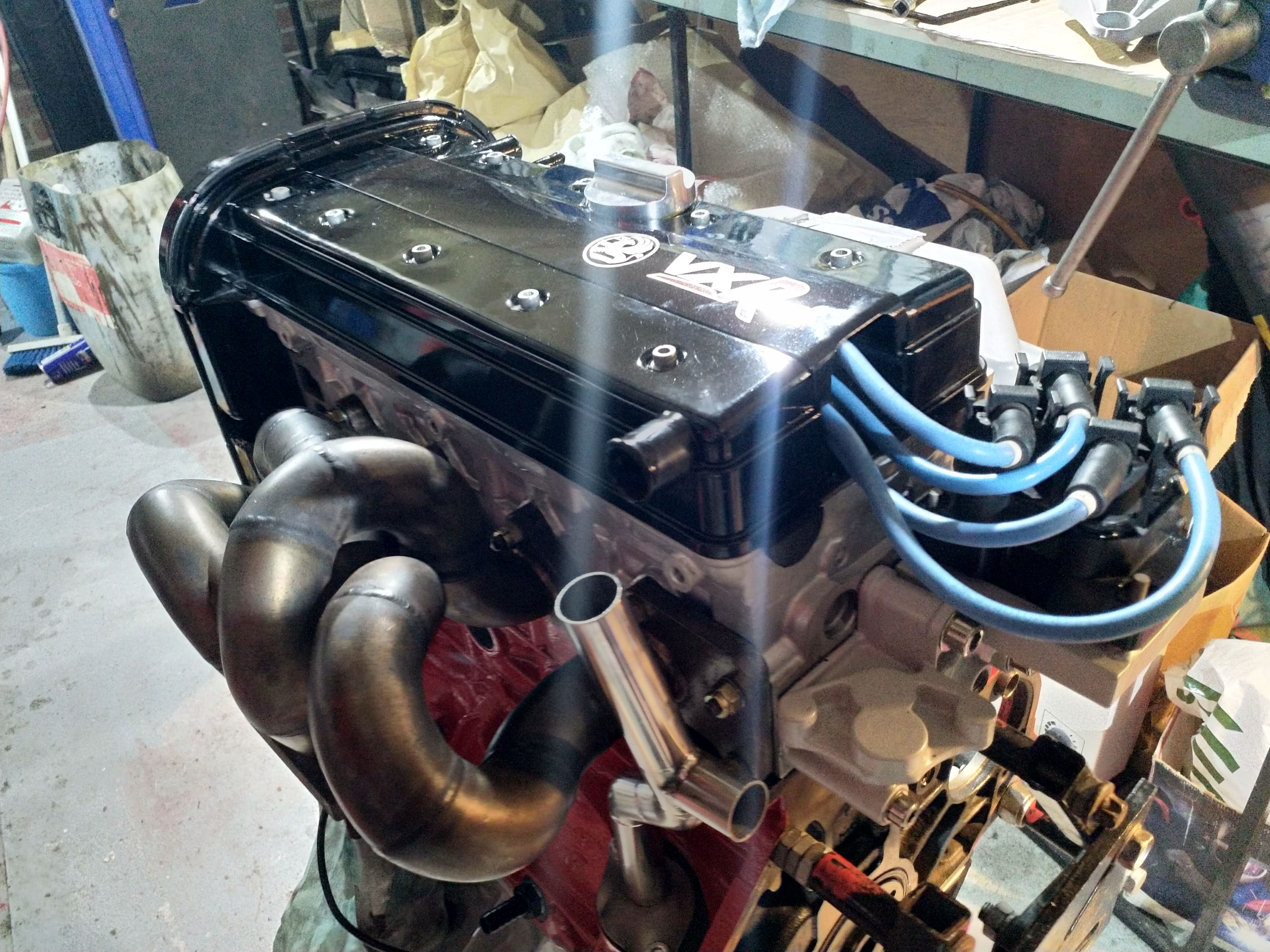
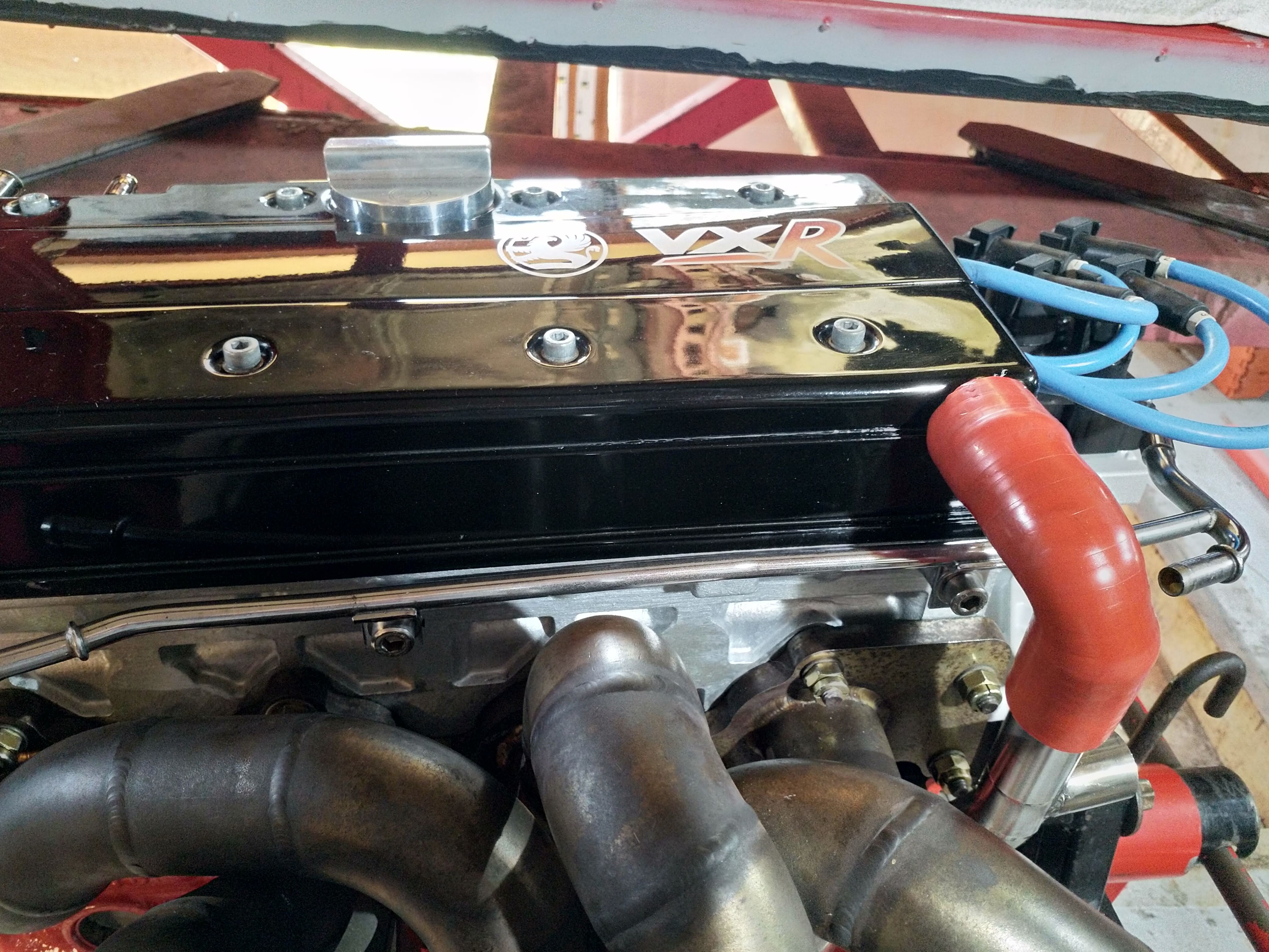
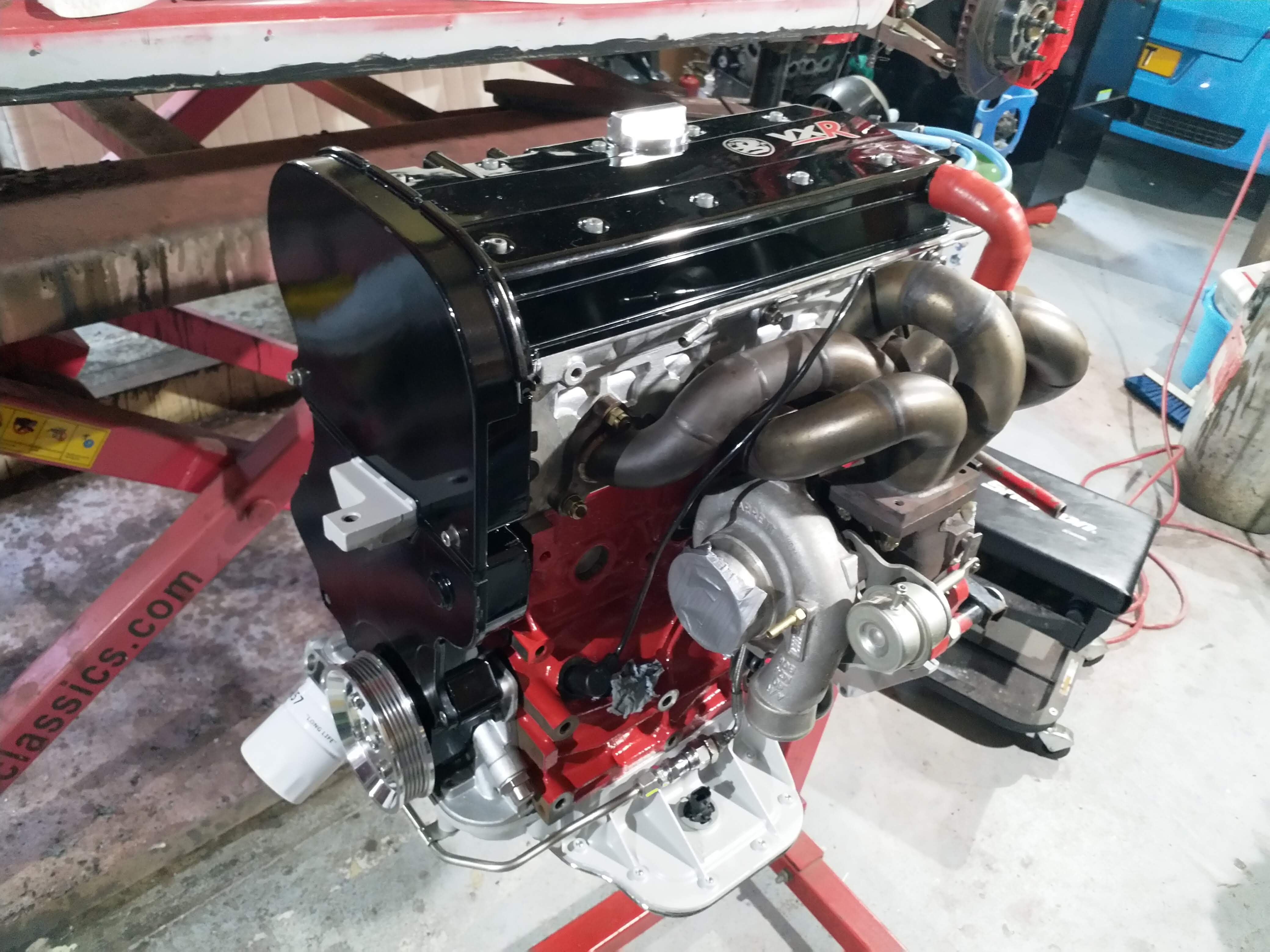
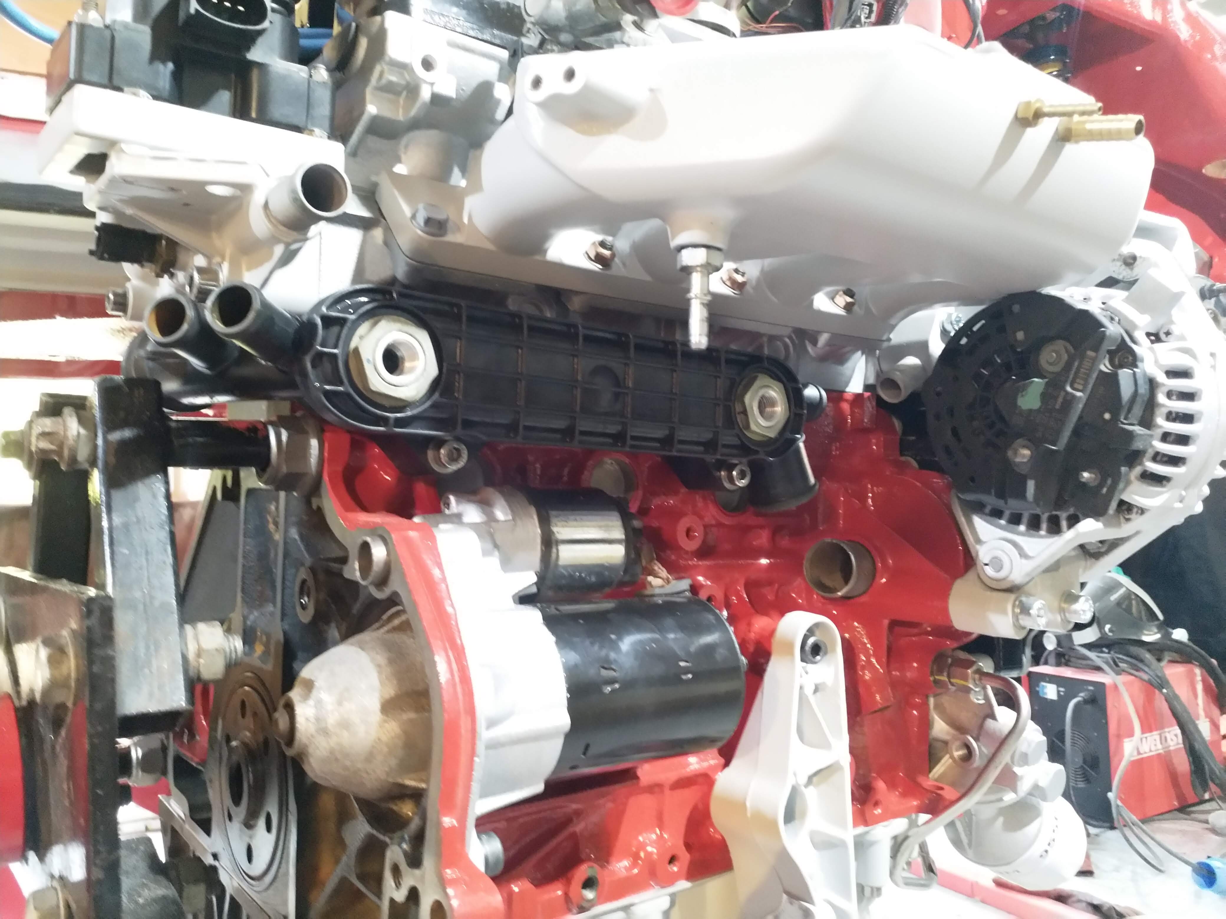
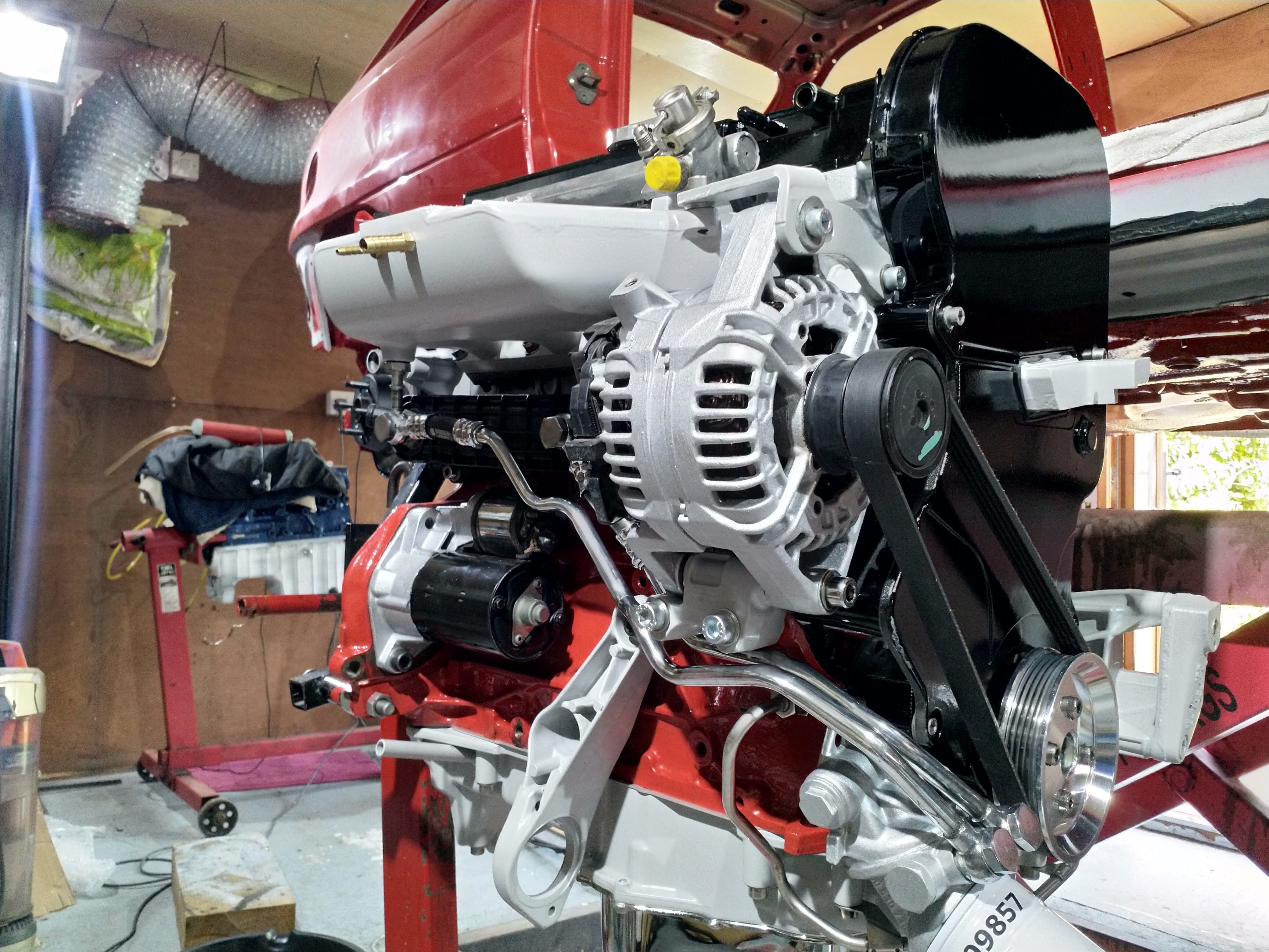
Look like a real engine now!
Next I checked the cam timing. I didn't get any pictures of this, but basically It is to check the cams are where they should be and I don't need to buy vernier pulleys.
Very briefly.....

Use a DTI gauge to find tdc, but also the piston is at tdc for a fair few degrees, so by finding the duration of TDC in degrees, you find absolute TDC.
Fit a timing disc with a pointer and put this at 0 degrees
Then Put a dti on the bucket and find full lift ( when the bucket is furthest down and valve full open)
Measure this 0.10mm before and after full lift, again the valve will be at full lift for a certain duration
Check on what angle of the crank full lift opening and full lift closing happens
find the average of these measurements and that will give you your degrees of full lift and check this against the cam specs.

My both my cam specs are full lift at 110 degrees ( after TDC and BDC )
Now each tooth on the pulley wheel is worth 6 degrees I was told

My cams came out at 108.5 degrees and 108.25 degrees. Which means they are a third of a tooth out :lol: I'll take that. Basically perfect. Certainly not enough to chase in a turbo car as it will make so little difference, the cost of new pullies just isn't worth it.

So i'm a happy bunny, engine turns over, everything went together well, bit push and I can get this done!
 
Great update Dave, love seeing it all coming together now.. do you want to rebuild my engine..? :lol:
 
Great update Dave, love seeing it all coming together now.. do you want to rebuild my engine..? :lol:
Cheers Tom lol, I think i'm a bit far away otherwise I would actually! I've had people ask me to do body work, that gets a hell no! But rebuilding engines is fun!
My neighbour who builds race engines on the side will have to retire one day, I was thinking about taking over his business lol
 
Exhaust manifold nuts, proper aerotight nuts

full


rocker cover, timing covers on, accessory pulley polished and fitted

full


inlet manifold, oil heat exchanger and bracket for the coil pack fitted

full


full


Coilpack and leads on

full


Breather tube

full


Turbo return polished up

full


full


full


Turbo on with support bracket, every bolt if a cap head as you can see :lol:

full


full


full


full


Looking pretty good!

full


full


Sensors in

full


Hose fittings

full


Then i end up having a really weird problem! The alternator didn't fit lol
I can only assume that the powdercoat is thicker?! :lol:

Only kidding, i'm assuming because the manifold was fitted after the alternator it was held up higher and bolted up higher. But i did alway hear that this might be an issue. So I spent a while grinding back the casing and made it fit

full


Had to space the alternator bracket upwards aswell. It all a bit strange. It's almost like the casting on the block is higher up. Weird. Its on there now though

full

Oil cooler on

full


cooler pipes polished and fitted

full


full


full


full


full


full


full


full


More soon

full
 

Users who are viewing this thread

Back
Top